Mazda 6 Service Manual: Drive shaft (mtx) disassembly/assembly
1. Disassemble in the order indicated in the table.
2. Assemble in the reverse order of disassembly.
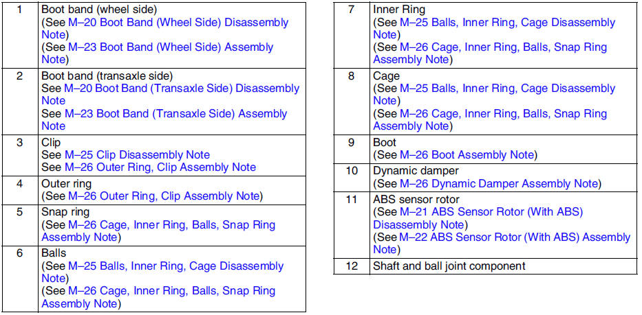
Clip Disassembly Note
1. Mark the drive shaft and outer ring for proper assembly.
Caution
- Mark with paint; do not use a punch.
2. Remove the clip.
Balls, Inner Ring, Cage Disassembly Note
1. Mark the inner ring and cage.
Caution
- Mark with paint; do not use a punch.
2. Remove the snap ring using snap-ring pliers.
3. Turn the cage approximately 30 degree
and pull the cage and balls away from the inner ring.
Dynamic Damper Assembly Note
1. Install the dynamic damper as shown in the figure.
Standard length334.7-340.7 mm {13.2-13.4 in}
2. Install the new boot band onto the dynamic damper.
Boot Assembly Note
Note
- The wheel side and transaxle side boots are different.
1. Fill the boot (wheel side) with the specified grease.
Caution
- Do not touch grease with your hand. Apply it from the tube to prevent foreign matter from entering the boot.
Grease amount
90-110 g {3.18-3.88 oz} (L8, LF left side) 105-125 g {3.71-4.40 oz} (L8, LF right side and L3)
2. With the splines of the shaft still wrapped in tape from disassembly, install the boot.
3. Remove the tape.
Cage, Inner Ring, Balls, Snap Ring Assembly Note
1. Align the marks and install the balls and cage to the inner ring in the direction shown in the figure.
Caution
- Install the cage with the offset facing the snap ring groove. If incorrectly installed, the drive shaft may become disengaged.
2. Install a new snap ring.
Outer Ring, Clip Assembly Note
1. Fill the outer ring and boot (transaxle side) with the specified grease.
Caution
- Do not touch grease with your hand. Apply it from the tube to prevent foreign matter from entering the boot.
Grease amount
105-125 g {3.71-4.40 oz} (L8, LF left side), 120-140 g {4.24-4.93 oz} (L8, LF right side and L3)
2. Align the marks, and install the outer ring on to the shaft.
3. Install a new clip.
4. Install the boot.
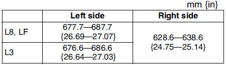
5. Set the drive shaft to the standard length.
Standard length
6. Release any trapped air from the boots by carefully lifting up the small end of each boot with a cloth wrapped screwdriver.
Caution
- Be careful not to allow the grease to leak.
- Do not damage the boot.
7. Verify that the drive shaft length is within the specification.
 Drive shaft (atx) disassembly/assembly
1. Disassemble in the order indicated in the table.
2. Assemble in the reverse order of disassembly.
Boot Band (Wheel Side) Disassembly Note
Note
The boot band does not need to be removed unle ...
 Steering system
...
Other materials:
Mazda 6 Service Manual: Driving Tips
WARNING
Do not let the vehicle move in a direction opposite to the direction selected
by the selector lever: Do not let the vehicle move backward with the selector
lever in a forward position, or do not let the vehicle move forward with the selector
lever in the reverse position. Otherwise, t ...
Mazda 6 Service Manual: Noise filter inspection
Brake Light Noise Filter
1. Inspect for resistance and continuity between the noise filter terminals
using an ohmmeter.
If not as specified, replace the noise filter.
Rear Window Defroster Noise Filter
Inspect for resistance and continuity between the noise filter terminals
using an ...