Mazda 6 Service Manual: Dsc hu/cm inspection
1. Remove the battery and battery bracket.
2. Disconnect the DSC HU/CM connector.
3. Connect the SST
(49 G066 004) to the DSC HU/CM connector and harness side connector.
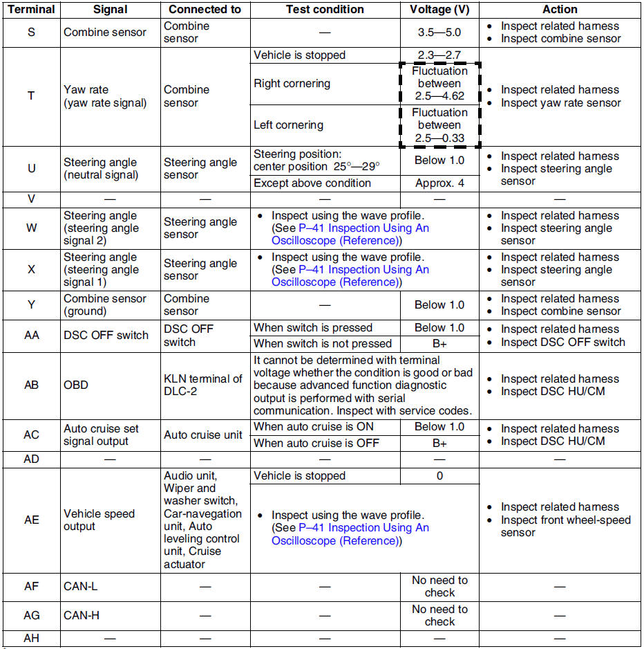
4. Inspect voltage referring the table below.
Terminal Voltage Table (reference value)
(Ignition switch is at ON, and connector is connected unless indicated otherwise.)
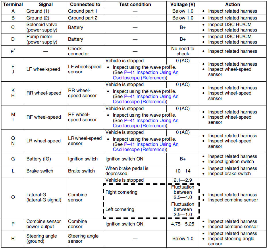
* : Used for vehicle manufacturing, not used for DSC.
Inspection Using An Oscilloscope (Reference)
Steering angle (steering angle signal 1 and 2)
- DSC HU/CM terminal:
Steering angle signal 2 : W ( + ) - R ( - )
Steering angle signal 1 : X ( + ) - R ( - )
- Oscilloscope setting:
1 V/DIV (Y), 25 ms/DIV (X), DC range
- Vehicle condition: Rotating steering wheel at one revolution per second
Note
- As steering wheel rotation speed increases, period of wave shortens.
- As for shape of steering angle signals 1 and 2, the phase is different.
Wheel speed
- DSC HU/CM terminal:
RF : M ( + ) - I ( - )
RR : K ( + ) - H ( - )
LF : F ( + ) - J ( - )
LR : Q ( + ) - N ( - )
- Oscilloscope setting:
1 V/DIV (Y), 2 ms/DIV (X), AC range
- Vehicle condition: Driving 30 km/h (18.6 mph)
Note
- As vehicle speed increases, period of wave shortens.
- If there is malfunctioning in the sensor rotor, wave profile warps.
Vehicle speed output
- DSC HU/CM terminal: AE ( + ) - A( - )
- Oscilloscope setting:
1 V/DIV (Y), 5 ms/DIV (X), DC range
- Vehicle condition: Driving 30 km/h (18.6 mph)
Note
- As vehicle speed increases, period of wave shortens.
 Dsc hu/cm removal/installation
Caution
When replacing the DSC HU/CM, configuration procedure must be done
before removing the DSC HU/CM. If configuration is not completed before
removing the DSC HU/CM, DTC B2477 will be d ...
 Combine sensor removal/installation
Caution
Be careful and do not allow the combine sensor to fall. If by
chance it is subjected to strong impact, replace it.
1. Remove the center console.
2. Remove in the order indicated in ...
Other materials:
Mazda 6 Service Manual: Traffic Sign Display Indication
The following traffic signs are displayed on the active driving display.
Speed limit signs
Do not enter signs
Stop signs
The above indications are some examples.
NOTE
Speed limit signs
When the vehicle speed is about 1 km/h (0.6 mph) or faster, the speed
limit sign is displayed wh ...
Mazda 6 Service Manual: Operating Tips for CD Player
Condensation phenomenon
Immediately after turning on the heater when the vehicle is cold, the CD or optical
components (prism and lens) in the CD player may become clouded with condensation.
At this time, the CD will eject immediately when placed in the unit. A clouded CD
can be corrected sim ...