Mazda 6 Service Manual: Fuel injector inspection
Operation Test
Carry out the Fuel Injector Operation Inspection. (See Fuel Injector Operation Inspection.)
- If not as specified, perform the further inspection for the fuel injectors.
Resistance Inspection
Note
- Perform the following test only when directed.
1. Turn the ignition switch to LOCK position.
2. Disconnect the negative battery cable.
3. Disconnect the fuel injector connectors.
4. Measure the resistance of the fuel injector using an ohmmeter.
- If not as specified, replace the fuel injector. (See FUEL INJECTOR REMOVAL/INSTALLATION.)
- If as specified but Operation Test is failed, carry out the Circuit Open/Short Inspection. Inspect for open or short circuit.
Resistance
11.4-12.6 ohms [20 ° C {68 ° F}]
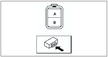
Circuit Open/Short Inspection
1. Disconnect the PCM connector. (See PCM REMOVAL/INSTALLATION.)
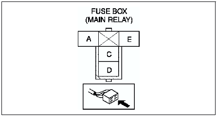
2. Inspect the following wiring harness for open or short (continuity check).
Open circuit
- If there is no continuity, the circuit is open. Repair or replace the harness.
- No.1 cylinder fuel injector terminal B (harness-side) and PCM terminal 4Z.
- No.2 cylinder fuel injector terminal B (harness-side) and PCM terminal 4W.
- No.3 cylinder fuel injector terminal B (harness-side) and PCM terminal 4AD.
- No.4 cylinder fuel injector terminal B (harness-side) and PCM terminal 4AA.
- No.1 cylinder fuel injector terminal A (harness-side) and main relay (harness-side) terminal C through common connector.
- No.2 cylinder fuel injector terminal A (harness-side) and main relay (harness-side) terminal C through common connector.
- No.3 cylinder fuel injector terminal A (harness-side) and main relay (harness-side) terminal C through common connector.
- No.4 cylinder fuel injector terminal A (harness-side) and main relay (harness-side) terminal C through common connector.
Short circuit
- If there is continuity, the circuit is short. Repair or replace the harness.
- No.1 cylinder fuel injector terminal B (harness-side) and body GND.
- No.2 cylinder fuel injector terminal B (harness-side) and body GND.
- No.3 cylinder fuel injector terminal B (harness-side) and body GND.
- No.4 cylinder fuel injector terminal B (harness-side) and body GND.
- No.1 cylinder fuel injector terminal A (harness-side) and power supply.
- No.2 cylinder fuel injector terminal A (harness-side) and power supply.
- No.3 cylinder fuel injector terminal A (harness-side) and power supply.
- No.4 cylinder fuel injector terminal A (harness-side) and power supply.
Fuel Leakage Inspection
Warning
- Fuel line spills and leakage are dangerous. Fuel can ignite and cause serious injuries or death and damage. Always carry out the following procedure with the engine stopped.
Note
- Perform the following test only when directed.
1. Complete the BEFORE REPAIR PROCEDURE. (See BEFORE REPAIR PROCEDURE.)
2. Disconnect the negative battery cable.
3. Remove the fuel injectors together with the fuel distributor with the fuel hose connected. (See FUEL INJECTOR REMOVAL/INSTALLATION.)
4. Fasten the fuel injectors firmly to the fuel distributor with wire.
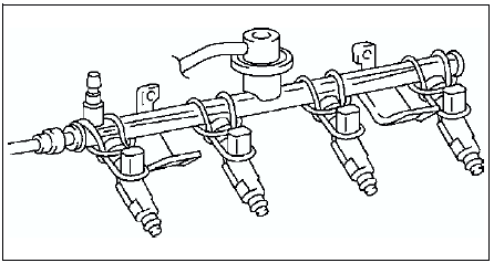
5. Connect the negative battery cable.
Caution
- Connecting the wrong check connector terminal may possibly cause malfunction. Carefully connect the specified terminal only.
6. Short the check connector terminal F/P to body GND using a jumper wire.
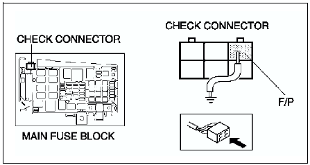
7. Turn the ignition switch to ON position to operate the fuel pump.
8. Tilt the fuel injectors approx. 60 degrees.
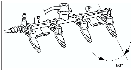
9. Verify that fuel leakage from the fuel injector nozzles is within the specification.
- If not as specified, replace the fuel injector.
Fuel leakage
Less than 1 drop/2 minutes
10. Turn the ignition switch to LOCK position and remove the jumper wire.
11. Complete the AFTER REPAIR PROCEDURE. (See AFTER REPAIR PROCEDURE.)
Volume Inspection
Warning
- Fuel line spills and leakage are dangerous. Fuel can ignite and cause serious injuries or death and damage. Always carry out the following procedure with the engine stopped.
Note
- If there is an after market fuel injector tester, perform the following test.
- If there is no an after market fuel injector tester, perform Operation Test, Resistance Inspection, and Fuel Leakage Test to verify the fuel injector is okay or not.
1. Complete the BEFORE REPAIR PROCEDURE. (See BEFORE REPAIR PROCEDURE.)
2. Disconnect the negative battery cable.
3. Remove the fuel injectors. (See FUEL INJECTOR REMOVAL/INSTALLATION.)
4. Connect the fuel injector to the fuel injector tester.
5. Measure the injection volume of each fuel injector using a graduated container.
- If not as specified, replace the fuel injector.
Injection volume
L3: 61-71 ml {61-79 cc, 2.2-2.7 fl oz}/15 sec.LF: 53-69 ml {53-69 cc, 1.9-2.4 fl oz}/15 sec.
L8: 48-63 ml {48-63 cc, 1.7-2.2 fl oz}/15 sec.
6. Turn the ignition switch to LOCK position and disconnect the jumper wire.
7. Complete the AFTER REPAIR PROCEDURE. (See AFTER REPAIR PROCEDURE.)
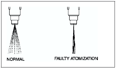
Atomization
Inspect atomization pattern.
- If the atomization is faulty, replace the fuel injector.
PRESSURE REGULATOR INSPECTION
Note
- Due to the adoption of the mechanical returnless fuel system, the pressure regulator cannot be inspected separately.
Perform FUEL LINE PRESSURE INSPECTION. (See FUEL LINE PRESSURE INSPECTION.)
PULSATION DAMPER REMOVAL/INSTALLATION
1. Remove and install the pressure regulator.(See FUEL INJECTOR REMOVAL/INSTALLATION.)
PULSATION DAMPER INSPECTION
1. Complete the BEFORE REPAIR PROCEDURE. (See BEFORE REPAIR PROCEDURE.)
2. Remove the pulsation damper. (See PULSATION DAMPER REMOVAL/INSTALLATION.)
3. Visually inspect the pulsation damper for damage and cracks. Also verify that there is no extreme rust which will cause fuel leakage.
- If either is observed, replace the pulsation damper.
4. Complete the AFTER REPAIR PROCEDURE. (See AFTER REPAIR PROCEDURE.)
 Fuel injector removal/installation
Caution
Disconnecting/connecting the quick release connector without
cleaning it may possibly cause damage to the fuel pipe and quick release
connector. Always clean the quick release connec ...
 Exhaust system
EXHAUST SYSTEM INSPECTION
Start the engine and inspect each exhaust system component for exhaust gas
leakage.
If leakage is found, repair or replace as necessary.
EXHAUST SYSTEM REMOVAL/INST ...
Other materials:
Mazda 6 Service Manual: Sunroof unit disassembly/assembly
1. Disconnect the negative battery cable.
2. Remove the deflector.
3. Remove the glass panel.
4. Disassemble in the order indicated in the table.
5. Assemble in the reverse order of disassembly.
Slider Disassembly Note
1. Remove the screw.
2. Slide the slider rearward, and remove it fro ...
Mazda 6 Service Manual: Operating the Compact Disc (CD) Player
NOTE
If a disc has both music data (CD-DA) and MP3/WMA/AAC files, playback of the
two or three file types differs depending on how the disc was recorded.
Inserting the CD
Insert the CD into the slot, label-side up. The auto-loading mechanism will set
the CD and begin play.
NOTE
There wi ...
