Mazda 6 Service Manual: Abs (abs/tcs) hu/cm inspection
1. Disconnect the negative battery cable.
2. Connect the SST
between the ABS (ABS/TCS) HU/CM and harness connector with the ignition switch off.
3. Attach the tester leads to the SST
and inspect voltage referring the table below.
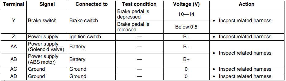
Terminal Voltage Table (Reference)
(Engine is idling, and connector is connected unless otherwise indicated.)
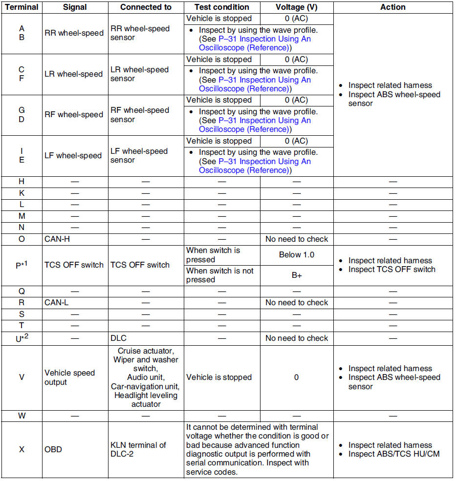
*1 : With TCS
*2 : Use this terminal at factory only, not used for inspection and repair at field
Inspection Using An Oscilloscope (Reference)
Wheel speed
- ABS/TCS HU/CM terminal:
RR : A ( + ) - B ( - )
LR : C ( + ) - F ( - )
RF : D ( + ) - G ( - )
LF : E ( + ) - I ( - )
- Oscilloscope setting:
1 V/DIV (Y), 2 ms/DIV (X), AC range
- Vehicle condition: Driving 30 km/h (18.6 mph)
Note
- As vehicle speed increases, period of wave shortens.
- If there is malfunctioning in the sensor rotor, wave profile warps.
Vehicle speed output
- ABS/TCS HU/CM terminal: V( + ) - AC ( - )
- Oscilloscope setting:
1 V/DIV (Y), 5 ms/DIV (X), DC range
- Vehicle condition: Driving 30 km/h (18.6 mph)
Note
- As vehicle speed increases, period of wave shortens.
 Abs (abs/tcs) or dsc hu/cm configuration
1. Connect the WDS or equivalent to the DLC-2.
2. Input vehicle information following the direction on the WDS or equivalent
screen.
3. Select Module programming.
4. Select Programmable module ...
 Tcs (dsc) off switch removal/installation
1. Press the hooks of the TCS OFF switch and pull the switch out.
2. Disconnect the connector.
3. Install in the reverse order of removal. ...
Other materials:
Mazda 6 Service Manual: Dtc c1095, c1096
Caution
When attaching the tester lead to the ABS (ABS/TCS) HU/CM harnesses
connector the SST (49 G066 001) must be used. (See ABS (ABS/TCS) HU/CM
INSPECTION.)
Diagnostic procedure
...
Mazda 6 Service Manual: Audio Set
NOTE
The explanation of functions described in this manual may differ from the
actual operation, and the shapes of screens and buttons and the letters and characters
displayed may also differ from the actual appearance.
Additionally, depending on future software updates, the content may succes ...