
Mazda 6 Service Manual: Fuel pump unit removal/installation
Warning
- Fuel line spills and leakage are dangerous. Fuel can ignite and cause serious injuries or death and damage. Fuel can also irritate skin and eyes. To prevent this, do not damage the sealing surface of the fuel pump unit when removing or installing.
Caution
- Disconnecting/connecting the quick release connector without cleaning it may possibly cause damage to the fuel pipe and quick release connector. Always clean the quick release connector joint area before disconnecting/connecting using a cloth or soft brush, and make sure that it is free of foreign material.
1. Complete the BEFORE REPAIR PROCEDURE. (See BEFORE REPAIR PROCEDURE.)
2. Disconnect the negative battery cable.
3. Remove the rear seat cushion.
4. Remove in the order indicated in the table.
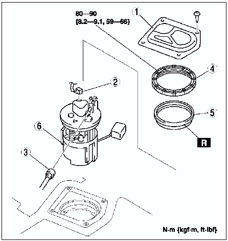
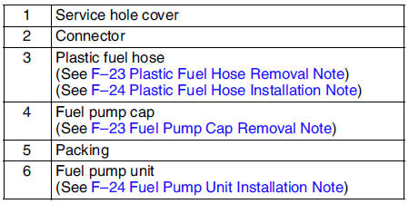
5. Install in the reverse order of removal.
6. Complete the AFTER REPAIR PROCEDURE. (See AFTER REPAIR PROCEDURE.)
Plastic Fuel Hose Removal Note
Caution
- The quick release connector may be damaged if the tab is bent excessively. Do not expand the tab over the stopper.
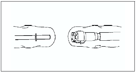
1. Disconnect the quick release connector.
(1) Push the tab on the locking coupler 90 degrees
until it stops.
(2) Pull the fuel hose straight back.
Note
- The stopper may be removed from the quick connector. Take care not to lose it.
Reinstall it to the quick release connector before reconnecting the fuel line.
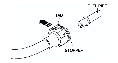
- The locking coupler has two internal locking tabs which retain the fuel pipe. Be sure that the tab on the locking coupler is rotated until it stops to release two internal locking tabs.
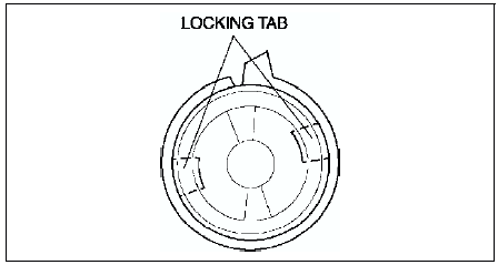
2. Cover the disconnected quick release connector and fuel pipe with vinyl sheets or the like to prevent them from being scratched or contaminated with foreign material.
Fuel Pump Cap Removal Note
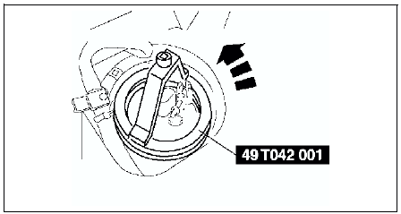
Using the SST
, remove the fuel pump unit.
Fuel Pump Unit Installation Note
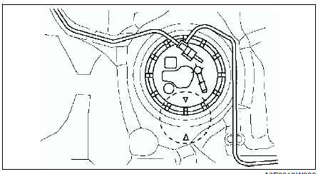
Verify that the fuel tank mark is aligened with the fuel pump mark as shown.
Plastic Fuel Hose Installation Note
Note
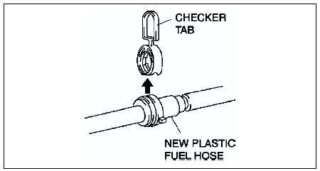
- A checker tab is integrated with quick release connector for new plastic fuel hoses. The checker tab will be released from the quick release connector after it is completely engaged with the fuel pipe.
1. When the retainer is not removed, perform the following procedure.
(1) Inspect the fuel pump unit sealing surface for damage and deformation, and replace as necessary.
- If the quick release connector O-ring is damaged, replace the plastic fuel hose.
(2) Slightly apply clean engine oil to the sealing surface of the fuel pump unit.
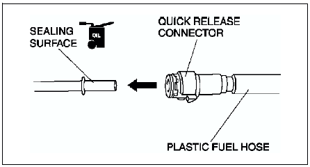
(3) Align the fuel pipe on the fuel pump unit and quick release connector so that the tabs of the retainer are correctly fitted into the quick release connector. Push the quick release connector straight into the retainer until a click is heard.
(4) Lightly pull and push the quick release connector a few times by hand and verify that it can move 2.0-3.0 mm {0.08-0.11 in}
and it is connected securely.
- If quick release connector does not move at all, verify that O-ring is not damaged and slipped, and reconnect the quick release connector.
2. When the retainer is removed, perform the following procedure.
 Fuel line pressure inspection
Warning
Fuel line spills and leakage are dangerous. Fuel can ignite and
cause serious injuries or death. Fuel can also irritate skin and eyes. To
prevent this, always complete the BEFORE REP ...
 Fuel pump unit disassembly/assembly
Warning
Fuel line spills and leakage are dangerous. Fuel can ignite and
cause serious injuries or death and damage. Fuel can also irritate skin and
eyes. To prevent this, do not damage the s ...
Other materials:
Mazda 6 Service Manual: Keyless Entry System
This system uses the key buttons to remotely lock and unlock the doors and the
trunk lid, and opens the trunk lid.
The system can start the engine without having to take the key out of your purse
or pocket.
It can also help you signal for attention or help.
Operating the theft-deterrent syste ...
Mazda 6 Service Manual: Front Passenger Occupant Classification Sensor
Your vehicle is equipped with a front passenger occupant classification sensor
as a part of the supplemental restraint system. This sensor is equipped in the front
passenger's seat cushion. This sensor measures the electrostatic capacity of the
front passenger's seat. The SAS unit is designed ...