Mazda 6 Service Manual: Heated oxygen sensor (ho2s) inspection
HO2S Voltage Inspection
Note
- Perform the following inspection only when directed.
1. Warm up the engine and run it at idle.
2. Disconnect the HO2S connector.
3. Connect the voltmeter test leads to the following HO2S terminals:
- HO2S (front and rear)
- (+) leadterminal A
- (-) leadterminal B
4. With the vehicle stopped, run the engine at 3,000 rpm
until the voltmeter moves between 0.5 and 0.7 V.
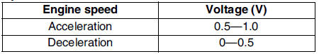
5. Verify that the measurement voltage changes when the engine speed increases and decreases suddenly several times.
- If not as specified, replace the HO2S.
- If the HO2S is okay, but O2S11 or O2S12 PID value is out of specification, perform the Circuit Open/Short Inspection.
Specification
Circuit Open/Short Inspection (Sensor)
1. Disconnect the PCM connector. (See PCM REMOVAL/INSTALLATION.)
2. Inspect the following wiring harnesses for open or short. (Continuity check)
Open circuit
- If there is no continuity, the circuit is open. Repair or replace the harness.
Front
- HO2S terminal A (harness-side) and PCM terminal 1AB (harness-side)
- HO2S terminal B (harness-side) and PCM terminal 2H (harness-side)
Rear
- HO2S terminal A (harness-side) and PCM terminal 1Y (harness-side)
- HO2S terminal B (harness-side) and PCM terminal 2H (harness-side)
Short circuit
- If there is continuity, the circuit is shorted. Repair or replace the harness.
Front and Rear
- HO2S terminal A (harness-side) and body GND
- HO2S terminal A (harness-side) and power supply
- HO2S terminal B (harness-side) and power supply
HO2S Heater Resistance Inspection
1. Disconnect the HO2S connector.
2. Measure the resistance between the HO2S terminals C and D.
- If not as specified, replace the HO2S.
- If the HO2S heater is okay, but PID value is out of specification, perform the Circuit Open/Short Inspection.
Specification
Front : 3.0-3.6 ohms
Rear : 5-7 ohms
Circuit Open/Short Inspection (Heater)
1. Disconnect the PCM connector. (See PCM REMOVAL/INSTALLATION.)
2. Inspect the following wiring harnesses for open or short. (Continuity check)
Open circuit
- If there is no continuity, the circuit is open. Repair or replace the harness.
Front
- HO2S terminal C (harness-side) and ignition switch
- HO2S terminal D (harness-side) and PCM terminal 4A (harness-side)
Rear
- HO2S terminal C (harness-side) and ignition switch
- HO2S terminal D (harness-side) and PCM terminal 4D (harness-side)
Short circuit
- If there is no continuity, the circuit is shorted. Repair or replace the harness.
Front and rear
- HO2S terminal C (harness-side) and body GND
- HO2S terminal D (harness-side) and power supply
- HO2S terminal D (harness-side) and body GND
 Knock sensor removal/installation
1. Remove the intake manifold. (See INTAKE-AIR SYSTEM REMOVAL/INSTALLATION.)
2. Remove the knock sensor attachment bolt to remove the knock sensor.
3. Install in the reverse order of removal.
...
 Power steering pressure (psp) switchinspection
Note
Perform the following inspection only when directed.
Continuity Inspection
1. Inspect the following if the power steering is inoperative (See POWER
STEERING FLUID INSPECTION.):
Powe ...
Other materials:
Mazda 6 Service Manual: Control system
L.H.D.
R.H.D.
...
Mazda 6 Service Manual: Recommended Tire Inflation Pressure
On the tire label you will find the recommended tire inflation pressure in both
kPa and psi for the tires installed as original equipment on the vehicle. It is
very important that the inflation pressure of the tires on your vehicle is maintained
at the recommended pressure.
You should check t ...