
Mazda 6 Service Manual: Magnetic clutch disassembly/assembly
1. Disassemble in the order indicated in the table.
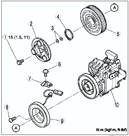
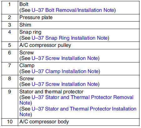
2. Assemble in the reverse order of disassembly.
3. Adjust the magnetic clutch clearance. (See MAGNETIC CLUTCH ADJUSTMENT.)
Bolt Removal/Installation Note
1. When removing or installing the bolt, hold the pressure plate in place as shown in the figure.
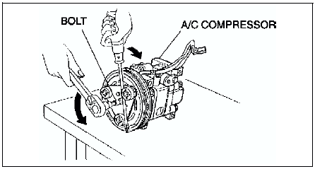
2. When installing a new A/C compressor body, replace the bolt.
Stator and Thermal Protector Removal Note
After removing the stator and thermal protector, completely remove the silicone adhering to the A/C compressor side.
Stator and Thermal Protector Installation Note
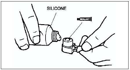
Apply approximately 1 g {0.04 oz} of silicone (Shin-Etsu Silicone KE-347W or similar) to the contact surface of the thermal protector, then thoroughly install it onto the A/C compressor, leaving no gaps.
Screw Installation Note
When installing a new stator and thermal protector, replace the screw.
Clamp Installation Note
When installing a new stator and thermal protector, replace the clamp.
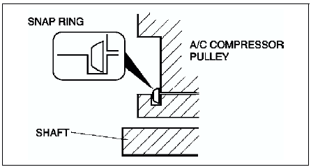
Snap Ring Installation Note
When installing a new pressure plate, A/C compressor pulley, stator, or A/C compressor body, replace the snap ring.
 Power mos fet inspection
Verify that the resistance between the terminals of the power MOS FET is as
shown in the table.
If not as specified, replace the power MOS FET.
...
 Magnetic clutch adjustment
1. Measure the clearance around the entire circumference between the pressure
plate and A/C compressor pulley using a thickness gauge.
2. Verify that the clearance is within the specification.
...
Other materials:
Mazda 6 Service Manual: Fuel injector removal/installation
Caution
Disconnecting/connecting the quick release connector without
cleaning it may possibly cause damage to the fuel pipe and quick release
connector. Always clean the quick release connector joint area before
disconnecting/connecting using a cloth or soft brush, and make sure that it ...
Mazda 6 Service Manual: Sas unit configuration
1. Connect the SST (WDS or equivalent) to the DLC-2.
2. Input vehicle information following the directions on the screen.
3. Select Module programming.
4. Select Programmable module installation.
5. Select the following items and perform procedures according to directions
on the screen.
...