Mazda 6 Service Manual: Master cylinder removal/installation
1. Remove in the order indicated in the table.
R.H.D.
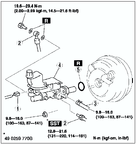
L.H.D.
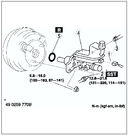
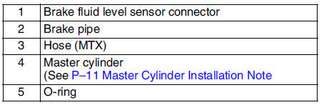
2. Install in the reverse order of removal.
Master Cylinder Installation Note
Caution
- Always install the gasket of the power brake unit push rod before performing measurement inspections or adjustments.
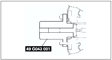
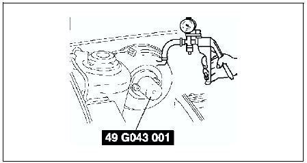
1. Install the SST
to the power brake unit as shown, and tighten within the specified torque.
Tightening torque 9.8-16.0 N·m {100-163 kgf·cm, 87-141 in·lbf}
2. Using a vacuum gauge, create a vacuum pressure of 66.7 kPa {500 mmHg, 19.7 inHg}
in the power brake unit.
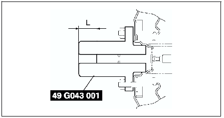
3. Using calipers, measure dimension L as shown.
Specification
22.7 mm{8.94 in}
4. If dimension L is not within the specification as shown, remove SST
(49 E043 001) and use SST
(49 B043 004) to adjust the length of the push rod while using SST
(E043 003A) to keep the push rod from rotating.
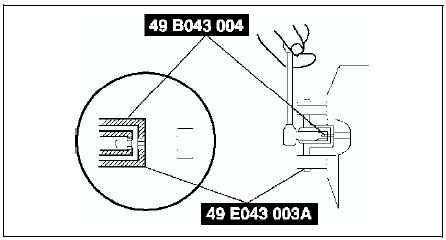
5. Remove the SSTs
, replace SST
(49 E043 001) and measure dimension L again.
6. Install the master cylinder to the power brake unit.
Caution
- If after installing the master cylinder, air does not bleed properly from the brake lines even after performing air bleeding, brake drag occurs or other characteristics are present, it is possible that the master cylinder piston is jammed against the power brake unit. If air cannot be bled properly, brake drag exists or other malfunctions occur, remove the master cylinder and reinstall properly.
 Brake pedal removal/installation
1. For ATX model, remove the lock unit with brake switch (R.H.D. only).
2. Remove in the order indicated in the table.
3. Install in the reverse order of removal.
Brake switch Installation Note ...
 Fluid level sensor inspection
1. Disconnect the negative battery cable.
2. Disconnect the sensor connector.
3. Inspect for continuity between terminals of fluid level sensor.
If not as specified, replace the fluid level sens ...
Other materials:
Mazda 6 Service Manual: Luggage Compartment
Loading golf bags
Golf bags can be carried in the luggage compartment.
Up to three golf bags can be carried in the luggage compartment.
Place each of the three golf bags into the luggage compartment with the bottom
of each bag pointed to the left, and then set the top of each bag so that it is ...
Mazda 6 Service Manual: Owner Maintenance Precautions
The owner or a qualified service technician should make these vehicle inspections
at the indicated intervals to ensure safe and dependable operation.
Bring any problem to the attention of an Authorized Mazda Dealer or qualified
service technician as soon as possible.
At Least Twice a Year (For ...