Mazda 6 Service Manual: Steering gear and linkage removal/installation
Caution
- Performing the following procedures without first removing the ABS wheel-speed sensor may possibly cause an open circuit in the harness if it is pulled by mistake. Before performing the following procedures, remove the ABS wheel-speed sensor (axle side) and fix it to an appropriate place where the sensor will not be pulled by mistake while servicing the vehicle.
1. Remove in the order indicated in the table.
2. Install in the reverse order of removal.
3. After installation, inspect the toe-in. (See FRONT WHEEL ALIGNMENT.)
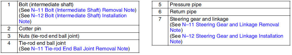
Bolt (Intermediate Shaft) Removal Note
Mark the pinion shaft and gear housing for proper installation.
Tie-rod End Ball Joint Removal Note
1. Remove the tie rod-nut.
2. Separate the tie-rod end from the steering knuckle using the SSTs
.
Steering Gear and Linkage Removal Note
L.H.D.
Caution
- Excessively loosening the crossmember nuts may possibly cause the crossmember to fall off. The crossmember nuts must remain threaded on the studs when loosening.
1. Support the crossmember using jack before removing the crossmember bracket.
2. Loosen the jack and lower the crossmember.
3. Remove the steering gear and linkage by pulling it from the left side.
R.H.D.
Remove the steering gear and linkage by pulling it from the right side.
Steering Gear and Linkage Installation Note
1. Loosely tighten bolts.
2. Tighten the mounting bracket bolts to the specified torque in the order shown.
Tightening torque 74.4-104.8 N·m {7.6-10.6 kgf·m, 55-77 ft·lbf}
3. Tighten the crossmember installation nuts. (L.H.D.)
Tightening torque Nut: 119.6-154.8 N·m {12.2-15.7 kgf·m, 89-114 ft·lbf} Bolt: 93.1-131.3 N·m {9.5-13.3 kgf·m, 69-96 ft·lbf}
Bolt (Intermediate Shaft) Installation Note
Align the marks and install the intermediate shaft and bolt.
 Steering shaft inspection
1. Inspect the following.
(1) Column bearing for damage
(2) Steering shaft length
Replace the steering shaft component as necessary.
Length
211.6 mm {8.3 in}
2. Inspect the til ...
 Steering gear and linkage disassembly
Caution
Place copper plates, rag, or similar material in a vise, when
securing the mounting bracket portion of the steering gear.
Disassemble in the order indicated in the table.
.
Tie ...
Other materials:
Mazda 6 Service Manual: Setting the System
When the MODE switch is pressed, the Mazda Radar Cruise Control (MRCC) main indication
(white) turns on and the vehicle speed and the distance between vehicles while in
headway control can be set.
NOTE
When the ignition is switched to ACC or OFF while the Mazda Radar Cruise
Control (MR ...
Mazda 6 Service Manual: Emergency Locking Mode
When the seat belt is fastened, it will always be in the emergency locking mode. In the emergency locking mode, the belt remains comfortable on the occupant and the retractor will lock in position during a collision.
If the belt is locked and cannot be pulled out, retract the belt once, and then ...