Mazda 6 Service Manual: Drive shaft removal/installation
Caution
- Performing the following procedures without first removing the ABS wheel-speed sensor may possibly cause an open circuit in the harness if it is pulled by mistake. Before performing the following procedures, remove the ABS wheel-speed sensor (axle side) and fix it to an appropriate place where the sensor will not be pulled by mistake while the vehicle is being serviced.
1. Drain the transaxle oil (left side). (See AUTOMATIC TRANSAXLE FLUID (ATF) REPLACEMENT.) (See TRANSAXLE OIL REPLACEMENT.)
2. Remove in the order indicated in the table.
3. Install in the reverse order of removal.
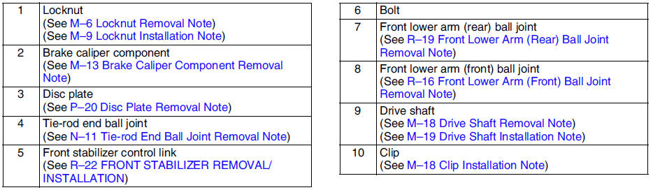
Drive Shaft Removal Note
1. Install a spare nut onto the drive shaft so that the nut is flush with the end of the drive shaft.
2. Tap the nut with a copper hammer to loosen the drive shaft from the front wheel hub.
3. Separate the drive shaft from the wheel hub.
Caution
- The sharp edges of the drive shaft can slice or puncture the oil seal. Be careful when removing the drive shaft from the transaxle.
4. Separate the left side drive shaft from the transaxle by prying with a bar inserted between the outer ring and the transaxle, as shown in the figure.
5. Install the SST
into the transaxle to hold the side gears after the drive shaft is removed.
Clip Installation Note
1. Install a new clip onto the joint shaft with the opening facing upward. Ensure that the diameter of the clip does not exceed the specification on installation.
2. After installation, measure the outer diameter. If it exceeds the specification, repeat Steps 1-2 using a new clip.
Outer diameter specification 31.2 mm {1.23 in} max.
Drive Shaft Installation Note
Caution
- The sharp edges of the drive shaft can slice or puncture the oil seal. Be careful when installing the drive shaft to the transaxle.
- The oil seals are damaged easily if this procedure is not done correctly.
1. Insert the drive shaft into the wheel hub.
2. Apply transaxle oil to the oil seal lip.
3. Push the drive shaft into the transaxle.
4. After installation, pull the transaxle side outer ring forward to confirm that the drive shaft is securely held by the clip.
 Drive shaft pre-inspection
1. Inspect the dust boot on the drive shaft for cracks, damage, leaking
grease, and looseness in the boot band.
2. Inspect the drive shaft for bends, cracks, and wear in the joint or
splines.
...
 Drive shaft (atx) disassembly/assembly
1. Disassemble in the order indicated in the table.
2. Assemble in the reverse order of disassembly.
Boot Band (Wheel Side) Disassembly Note
Note
The boot band does not need to be removed unle ...
Other materials:
Mazda 6 Service Manual: Procedures for determining the location of a malfunction
System Wiring Diadram
PCM
1. Check the display of DTC U0121 and/or U0155, using the SST (WDS or
equivalent). (See DTC TABLE.)
2. Referring to the following table, determine the malfunctioning part of the
CAN system.
ABS/TCS HU/CM or DSC HU/CM
1. Accec and monitor the PCM MSG and IC MSGo ...
Mazda 6 Service Manual: Driving on Uneven Road
Your vehicle's suspension and underbody can be damaged if driven on rough/uneven
roads or over speed bumps at excessive speeds. Use care and reduce speed when traveling
on rough/uneven roads or over speed bumps.
Use care not to damage the vehicle's underbody, bumpers or muffler(s) when driving ...