Mazda 6 Service Manual: Mechanical system test
Mechanical System Test Preparation
1. Engage the parking brake and use wheel chocks at the front and rear of the wheels.
2. Inspect the engine coolant. (See ENGINE COOLANT LEVEL INSPECTION.)
3. Inspect the engine oil. (See ENGINE OIL INSPECTION.)
4. Inspect the ATF levels. (See AUTOMATIC TRANSAXLE FLUID (ATF) INSPECTION.)
5. Inspect the idle speed and ignition timing in P position. (See IDLE SPEED INSPECTION.)(See IGNITION TIMING INSPECTION.)
6. Bring up the engine and transaxle to normal operating temperature.
Line Pressure Test
1. Perform mechanical system test preparation. (See Mechanical System Test Preparation.)
Warning
- Removing the square-head plug when the ATF is hot can be dangerous. Hot ATF can come out of the opening and badly burn you. Before removing the square-head plug, allow the ATF to cool.
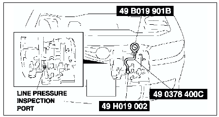
2. Connect the SSTs
(49 H019 002 and, 49 0378 400C) to the line pressure inspection port, then replace the gauge of the SST
(49 0378 400C) with the SST
(49 B019 901B).
3. Start the engine, then warm up the automatic transaxle.
4. Shift the selector lever to D range.
5. Read the line pressure at idle engine speed for the D range.
6. Read the line pressure at idle engine speed for the D (HOLD), S, S (HOLD), L, L (HOLD) ranges and R positions in the same manner as in Steps 4-5.
7. Stop the engine, then replace the SST
(49 B019 901B) with the gauge of the SST
(49 0378 400C).
8. Start the engine.
9. Firmly depress the brake pedal with the left foot.
10. Shift the selector lever to D range position.
Caution
- If the accelerator pedal is pressed for longer than 5 seconds while the brake pedal is pressed, the transaxle could be damaged. Therefore, perform Steps 11 and 12 within 5 seconds each.
11. Gradually depress the accelerator pedal with the right foot.
12. When the engine speed no longer increases, quickly read the line pressure and release the accelerator pedal.
13. Shift the selector lever to N position and let the engine idle for 1 minute or more to cool the ATF.
14. Read the line pressure at the engine stall speed for the D, D (HOLD), S, S (HOLD), L, L(HOLD) ranges and R position in the same manner as in Steps 9-13.
Specified line pressure
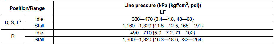
* : Includes each HOLD mode
Warning
- Removing the square-head plug when the ATF is hot can be dangerous. Hot ATF can come out of the opening and badly burn you. Before removing the square-head plug, allow the ATF to cool.
15. Remove the SSTs
.
16. Install a new square head plug in the inspection port.
Tightening torque 5.0-9.8 N·m {50-100 kgf·cm, 44-86 in·lbf}
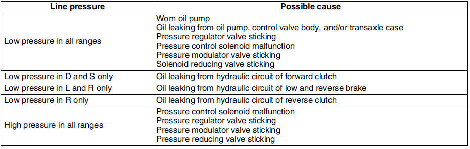
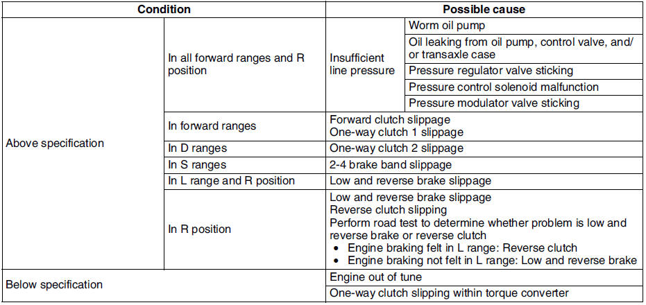
Evaluation of line pressure test
Stall Test
1. Perform mechanical system test preparation. (See Mechanical System Test Preparation.)
2. Start the engine.
3. Firmly depress the brake pedal with the left foot.
4. Shift the selector lever to D range.
Caution
- If the accelerator pedal is pressed for longer than 5 seconds while the brake pedal is pressed, the transaxle could be damaged. Therefore, perform Steps 5 and 6 within 5 seconds of each other.
5. Gently depress the accelerator pedal with the right foot.
6. When the engine speed no longer increases, quickly read the speed and release the accelerator pedal. When the engine speed no longer increases, quickly read the speed and release the accelerator pedal.
7. Shift the selector lever to N position and let the engine idle for 1 minute or more to cool the ATF.
8. Perform a stall test of D (HOLD), S, S (HOLD), L, L (HOLD) and R range positions in the same manner as in Steps 3-7.
9. Turn the ignition switch off.
Engine stall speed
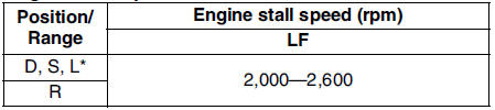
* : Includes each HOLD mode
Evaluation of stall test
Time Lag Test
1. Perform mechanical system test preparation. (See Mechanical System Test Preparation.)
2. Use a stopwatch to measure the time it takes from shifting until shock is felt when shifting the selector lever from N position to D range (non-HOLD mode). Take three measurements for each test and take the average from the results using the following formula.
Formula:
Average time lag = (Time 1 + Time 2 + Time 3) / 3
3. Perform the test for the following shifts in the same manner Step 2.
- N position → D range (HOLD mode)
- N position → R position
Time lag
N position → D range ... 0.4-0.7 s N position → R position ... 0.4-0.7 s
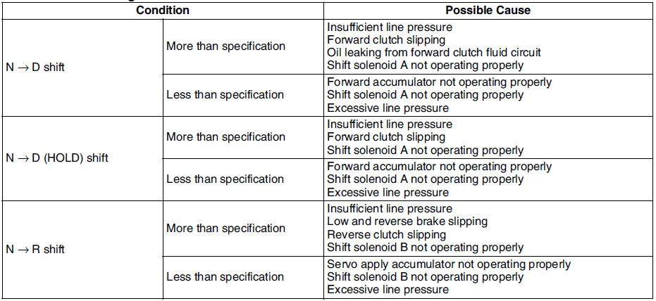
Evaluation of time lag test

 Road test
Warning
When performing a road test, be aware of other vehicles, people,
impediments, etc. to avoid an accident.
Note
When the legal speed limit must be exceeded, use a chassis
dynamo ...
Other materials:
Mazda 6 Service Manual: No.7 abs warning light stays on more than 4 seconds with ignition switch on
Diagnostic procedure
When performing an asterisked (*) troubleshooting inspection, shake the
wiring harness and connectors while doing the inspection to discover whether
poor contact points are the cause of any intermittent malfunction. If there is a
problem, check to make sure conne ...
Mazda 6 Service Manual: Rear door trim removal/installation
1. Disconnect the negative battery cable if equipped with power window
system.
2. Remove the regulator handle if equipped.
3. Open the cap using a small screwdriver, then remove the screw.
4. Remove the inner handle cover.
5. Remove the cover, then remove screw.
6. Disengage clips A from th ...