Mazda 6 Owners Manual: Windshield Wipers
Turn the wipers on by pressing the lever up or down.
With intermittent wiper
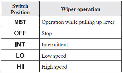
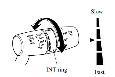
Variable-speed intermittent wipers
Set the lever to the intermittent position and choose the interval timing by rotating the ring.
With auto-wiper control
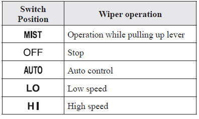
Auto-wiper control
When the wiper lever is in the
 position, the rain sensor senses
the amount of rainfall on the windshield and turns the wipers on or off automatically
(off— intermittent—low speed—high speed).
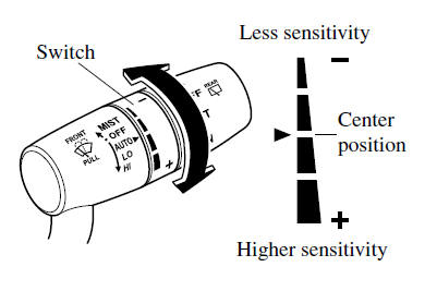
The sensitivity of the rain sensor can be adjusted by turning the switch on the wiper lever.
From the center position (normal), rotate the switch upward for higher sensitivity (faster response) or rotate it downward for less sensitivity (slower response).
CAUTION
Do not shade the rain sensor by adhering a sticker or a label on the windshield. Otherwise the rain sensor will not operate correctly.
- When the wiper lever is in the
position and the ignition
is switched ON, the wipers may move automatically in the following cases:- If the windshield above the rain sensor is touched or wiped with a cloth.
- If the windshield above the rain sensor is touched or wiped with a cloth.
- Keep hands and scrapers clear of the windshield when the wiper lever
is in the position and
the ignition is switched ON as fingers could be pinched or the wipers and wiper blades damaged when the wipers activate automatically.If you are going to clean the windshield, be sure the wipers are turned off completely (when it is most likely that the engine is left running) this is particularly important when clearing ice and snow.
NOTE
- Switching the auto-wiper lever from the
 to the
position while driving activates
the windshield wipers once, after which they operate according to the rainfall amount. - The auto-wiper control may not operate when the rain sensor temperature is about -10 °C (14 °F) or lower, or about 85 °C (185 °F) or higher.
- If the windshield is coated with water repellent, the rain sensor may not be able to sense the amount of rainfall correctly and the auto-wiper control may not operate properly.
- If dirt or foreign matter (such as ice or matter containing salt water)
adheres to the windshield above the rain sensor, or if the windshield is iced,
it could cause the wipers to move automatically.
However, if the wipers cannot remove this ice, dirt or foreign matter, the autowiper control will stop operation. In this case, set the wiper lever to the low speed position or high speed position for manual operation, or remove the ice, dirt or foreign matter by hand to restore the auto-wiper operation.
- If the auto-wiper lever is left in the
position, the wipers could
operate automatically from the effect of strong light sources, electromagnetic waves, or infrared light because the rain sensor uses an optical sensor. It is recommended that the auto-wiper lever be switched to the position other than when driving
the vehicle under rainy conditions. - If the headlight switch and the windshield wiper switch are in
, and the wipers are operated
at low or high speed by the auto wiper control for several seconds, bad weather conditions are determined and the headlights may be turned on. - The auto-wiper control functions can be turned off.
 Windshield Wipers and Washer
The ignition must be switched ON to use the wipers.
WARNING
Use only windshield washer fluid or plain water in the reservoir:
Using radiator antifreeze as washer fluid is dangerous. If sprayed on ...
 Windshield Washer
Pull the lever toward you and hold it to spray washer fluid.
NOTE
If the windshield washer is turned on when the windshield wipers are not operating,
the windshield wipers operate a few times.
...
Other materials:
Mazda 6 Owners Manual: Lane-keep Assist System (LAS) & Lane Departure Warning System (LDWS)
The Lane-keep Assist System (LAS) & Lane Departure Warning System (LDWS) alerts
the driver that the vehicle may be deviating from its lane and it provides steering
assistance to help the driver stay within the vehicle lanes.
The Forward Sensing Camera (FSC) detects the white lines (yellow l ...
Mazda 6 Owners Manual: Hazard Warning Flasher
The hazard warning lights should always be used when you stop on or near a roadway
in an emergency.
The hazard warning lights warn other drivers that your vehicle is a traffic hazard
and that they must take extreme caution when near it.
Depress the hazard warning flasher and all the turn s ...