Mazda 6 Service Manual: Cylinder head gasket
CYLINDER HEAD GASKET REPLACEMENT
Warning
- Fuel vapor is hazardous. It can very easily ignite, causing serious injury and damage. Always keep sparks and flames away from fuel.
- Fuel line spills and leakage are dangerous. Fuel can ignite and cause serious injuries or death and damage. Fuel can also irritate skin and eyes. To prevent this, always complete the Fuel Line Safety Procedure. (See Fuel Line Safety Procedure.)
1. Remove the timing chain. (See TIMING CHAIN REMOVAL/INSTALLATION.)
2. Remove the ignition coil. (See IGNITION COIL REMOVAL/INSTALLATION.)
3. Remove the high-tension lead. (See HIGH-TENSION LEAD REMOVAL/INSTALLATION.)
4. Disconnect the generator, but do not remove it from the vehicle. After disconnection, fix the generator using a rope to prevent it from falling. (See GENERATOR REMOVAL/INSTALLATION.)
5. Remove the front pipe. (See EXHAUST SYSTEM REMOVAL/INSTALLATION.)
6. Remove the intake manifold. (See INTAKE-AIR SYSTEM REMOVAL/INSTALLATION.)
7. Disconnect the heater hose, bypass hose, radiator hose.
8. To firmly support the engine, first set the engine jack and attachment to the oil pan.
Note
- A: MA-1
- B: M18MA
9. Remove in the order indicated in the table.
10. Install in the reverse order of removal.
11. Inspect the compression. (See COMPRESSION INSPECTION.)
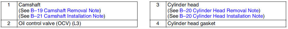
Camshaft Removal Note
Note
- The cylinder head and the camshaft caps are numbered to make sure they are reassembled in their original position. When removed, keep the caps with the cylinder head they were removed from. Do not mix the caps.
Loosen the camshaft cap bolts in several passes in the order shown.
Cylinder Head Removal Note
Loosen the cylinder head bolts in several passes in the order shown.
Cylinder Head Installation Note
1. Measure the length of each cylinder head bolt.
- Replace any that exceed maximum length.
Length L:
149.0-150.0 mm {5.867-5.905 in}Maximum:
150.5 mm {5.965 in}
2. Tighten the cylinder head bolts in the order shown using the following 5 steps.
(1) Tighten to 5.0 N·m {51.0 kgf·cm, 44.2 in·lbf}
(2) Tighten 13-17 N·m {1.4-1.7 kgf·m, 10.0-12.5 ft·lbf}
(3) Tighten 44-46 N·m {4.5-4.6 kgf·m, 32.5-33.9 ft·lbf}
(4) Tighten 88°-92°
(5) Tighten 88°-92°
Camshaft Installation Note
1. Set the cam position of the No.1 cylinder at the top dead center (TDC) and install the camshaft.
2. Temporarily tighten the camshaft bearing caps in two or three even movements.
3. Tighten the camshaft cap bolts in the order shown using the following two steps.
(1) Tighten to 5.0-9.0 N·m {51.0-91.7 kgf·cm, 44.6-79.5 in·lbf}
(2) Tighten to 14.0-17.0 N·m {1.5-1.7 kgf·m, 10.4-12.5 ft·lbf}
 Timing chain
TIMING CHAIN REMOVAL/INSTALLATION
Warning
Fuel vapor is hazardous. It can very easily ignite, causing
serious injury and damage. Always keep sparks and flames away from fuel.
Fuel line spill ...
 Front oil seal
FRONT OIL SEAL REPLACEMENT
1. Disconnect the negative battery cable.
2. Remove the spark plugs. (See SPARK PLUG REMOVAL/INSTALLATION.)
3. Remove the Cylinder head cover. (See Cylinder Head Cover In ...
Other materials:
Mazda 6 Service Manual: Front stabilizer removal/installation
1. Remove the front crossmember component. (See FRONT CROSSMEMBER
REMOVAL/INSTALLATION.)
2. Remove in the order indicated in the table.
3. Install in the reverse order of removal.
4. Adjust the headlight zeroset. (See HEADLIGHT ZEROSET.)
5. Inspect the front wheel alignment. (See FRONT WHEEL A ...
Mazda 6 Service Manual: Personalization Features
The following personalization features can be set or changed by the customer
or an Authorized Mazda Dealer. Consult an Authorized Mazda Dealer for details.
Additionally, some of the personalization features can be changed by the customer
depending on the feature.
Personalization features and s ...