Mazda 6 Service Manual: Flasher unit inspection
1. Connect the connector to the flasher unit.
2. Connect the negative battery cable.
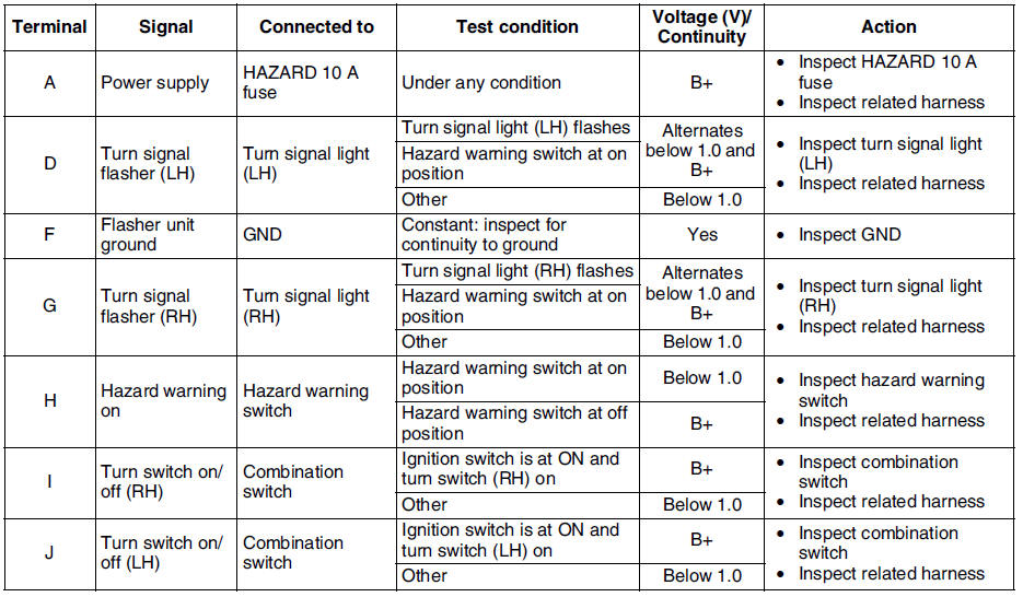
3. Measure the voltage at the flasher unit using voltmeter.
- When inspecting terminal F for continuity, disconnect the flasher unit connector.
4. If the value are not as specified in the Terminal Voltage List (Reference), inspect the parts under Action and related wiring harnesses.
5. If the system does not work properly even though the parts or related wiring harnesses do not have any malfunction, replace the flasher unit.
Terminal Voltage List (Reference)

 Flasher unit removal/installation
1. Disconnect the negative battery cable.
2. Remove the instrument cluster. (See INSTRUMENT CLUSTER REMOVAL/INSTALLATION)
3. Remove in the order indicated in the table.
4. Inst ...
 Running light unit removal/installation
Disconnect the negative battery cable.
2. Remove the glove compartment. (See GLOVE COMPARTMENT REMOVAL/INSTALLATION)
3. Remove in the order indicated in the table.
4. Install in ...
Other materials:
Mazda 6 Service Manual: Locking Lug Nuts
If your vehicle has Mazda optional antitheft wheel lug nuts, one on each wheel
will lock the tires and you must use a special key to unlock them. This key will
attach to the lug wrench.
Register them with the lock manufacturer by filling out the card provided in
the glove compartment and mail ...
Mazda 6 Service Manual: Stabilizer control link inspection
1. Remove the stabilizer control link from the vehicle.
2. Inspect for bending and damage.
3. Measure the ball joint starting torque.
(1) Rock the ball joint stud side to side 10 times.
(2) Rotate the ball joint stud 10 times.
(3) Measure the starting torque using a suitable allen so ...