Mazda 6 Service Manual: Front lower arm (front) removal/installation
1. Remove in the order indicated in the table.
2. Install in the reverse order of removal.
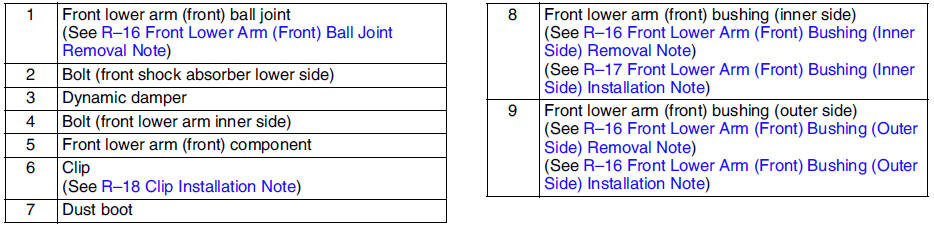
Front Lower Arm (Front) Ball Joint Removal Note
Separate the ball joint from the knuckle using the SSTs
.
Front Lower Arm (Front) Bushing (Inner Side) Removal Note
Press the bushing (inner side) out using the SSTs
.
Front Lower Arm (Front) Bushing (Outer Side) Removal Note
Press the bushing (outer side) out using the SSTs
.
Front Lower Arm (Front) Bushing (Outer Side) Installation Note
1. Mark the new bushing as shown in the figure.
2. Press the bushing in to the marking using the SSTs
.
3. Verify that clearance distance AB is 8.75 mm - 10.75 mm {0.3445 in - 0.4232 in}.
Front Lower Arm (Front) Bushing (Inner Side) Installation Note
1. Mark the new bushing as shown in the figure.

2. Press the bushing in to the marking using the SSTs
.
3. Verify that clearance distance AB is 12.75 mm - 14.75 mm {0.5020 in - 0.5807 in}.
Clip Installation Note
1. Wipe the grease off the ball stud.
2. Fill the inside of the new dust boot with grease.
3. Install the boot on the ball joint.
4. Install the new clip using the SST
.
5. Verify that the clip is installed securely to the groove.
6. Wipe away the excess grease.
 Front upper arm inspection
1. Remove the upper arm from the vehicle.
2. Inspect for damage, cracks, and bending.
3. Inspect the ball joint rotation torque.
(1) Rotate the ball joint five times.
(2) Measure the rotatio ...
 Front lower arm (front) inspection
1. Remove the lower arm (front) from the vehicle.
2. Inspect for damage, cracks, and bending.
3. Inspect the ball joint rotation torque.
(1) Rotate the ball joint five times.
(2) Measure the ...
Other materials:
Mazda 6 Service Manual: Evaporator temperature sensor inspection
1. Turn the AUTO switch on.
2. Set the temperature control at MAX COLD (Turn the left).
3. Turn the A/C switch.
4. Set the RECIRCULATE mode.
5. Close all doors and windows.
6. Wait for 5 minutes.
7. Remove the glove compartment.
8. Disconnect the evaporator temperature sensor.
9. Measure t ...
Mazda 6 Service Manual: Clock spring adjustment
Note
The adjustment procedure is also specified on the caution label of
the clock spring.
1. Set the front wheels straight ahead.
Caution
The clock spring will break if over-wound. Do not forcibly turn
the clock spring.
2. Turn the clock spring clockwise until it stops.
3. Tu ...