Mazda 6 Service Manual: Front lower arm (rear) removal/installation
1. Remove the front crossmember component. (See FRONT CROSSMEMBER REMOVAL/INSTALLATION.)
2. Remove in the order indicated in the table.
3. Install in the reverse order of removal.
4. Inspect the front wheel alignment. (See FRONT WHEEL ALIGNMENT.)
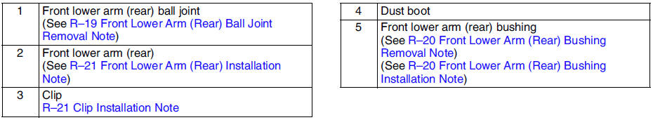
Front Lower Arm (Rear) Ball Joint Removal Note
Separate the ball joint from the knuckle using the SSTs
.
Front Lower Arm (Rear) Bushing Removal Note
1. Press the bushing out using the SSTs
.
2. Remove the front lower arm (rear) from the press and tap the bushing out with a hammer.
Front Lower Arm (Rear) Bushing Installation Note
1. Mark the new bushing as shown in the figure.
2. Press the bushing in to the marking using the SSTs
.
3. Verify that clearance distance AB is 23.75 mm - 25.75 mm {0.936 in - 1.013 in}.
Clip Installation Note
1. Wipe the grease off the ball stud.
2. Fill the inside of the new dust boot with grease.
3. Install the boot on the ball joint.
4. Install the new clip using the SST
.
5. Verify that the clip is installed securely to the groove.
6. Wipe away the excess grease.
Front Lower Arm (Rear) Installation Note
Install the lower arm (rear) so that identification mark (L or R) faces toward the front of the vehicle.
 Front lower arm (front) inspection
1. Remove the lower arm (front) from the vehicle.
2. Inspect for damage, cracks, and bending.
3. Inspect the ball joint rotation torque.
(1) Rotate the ball joint five times.
(2) Measure the ...
 Front lower arm (rear) inspection
1. Remove the lower arm (rear) from the vehicle.
2. Inspect for damage, cracks, and bending.
3. Inspect the ball joint rotation torque.
(1) Rotate the ball joint five times.
(2) Measure the ...
Other materials:
Mazda 6 Service Manual: Mounting the Spare Tire
1. Remove dirt and grime from the mounting surfaces of the wheel and hub, including
the hub bolts, with a cloth.
WARNING
Make sure the mounting surfaces of the wheel, hub and lug nuts are clean
before changing or replacing tires: When changing or replacing a tire, not
removing dirt and gri ...
Mazda 6 Service Manual: Fan motor
COOLING FAN REMOVAL/INSTALLATION
1. Disconnect the negative battery cable.
2. Remove the shroud panel. (See SHROUD PANEL REMOVAL/INSTALLATION.)
3. Remove the A/C pipe stay.
4. Remove the ATX pipe stay (ATX).
5. Remove in the order indicated in the table.
6. Install in the reverse order of remo ...