Mazda 6 Service Manual: Manual transaxle removal/installation
1. Remove the battery, battery tray and battery bracket.
2. Remove the air cleaner compornent. (See INTAKE-AIR SYSTEM REMOVAL/INSTALLATION.)
3. Remove the wheels, tires and splash shields.
4. Remove the under cover.
5. Remove the steering gear and power steering pipe. (See STEERING GEAR AND LINKAGE REMOVAL/INSTALLATION.)
6. Remove the front auto leveling sensor. (See FRONT AUTO LEVELING SENSOR REMOVAL/INSTALLATION.)
7. Drain the transaxle oil into a suitable container.
8. Remove in the order indicated in the table.
9. Install in the reverse order of removal.
10. Adjust the headlight zeroset. (See HEADLIGHT ZEROSET.)
11. Add the specified amount of specified transaxle oil.
12. Install the air cleaner compornent. (See INTAKE-AIR SYSTEM REMOVAL/INSTALLATION.)
13. Warm up the engine and transaxle, inspect for oil leakage, and inspect the transaxle operation.

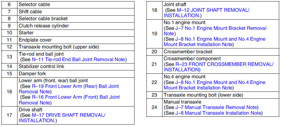
No.1 Engine Mount Bracket Removal Note
1. Support the engine using the SST before removing the No.1 engine mount.
2. Remove the No.1 engine mount.
Manual Transaxle Removal Note
1. Loosen the SST
(49 E017 5A0)and lean the engine toward the transaxle.
2. Support the transaxle on a jack.
3. Remove the transaxle mounting bolts.
4. Remove the transaxle.
Manual Transaxle Installation Note
1. Set the transaxle on a jack and lift into place.
2. Install the transaxle mounting bolts.
3. Tighten the SST
(49 E017 5A0)so that the engine is located at the specified position.
No.1 Engine Mount and No.4 Engine Mount Bracket Installation Note
1. Verify that the engine mount rubbers are installed as shown.
2. By aligning the holes with the stud bolts, install the No.4 engine mount bracket to the transaxle.
3. By aligning the holes with the stud bolts, install the No.1 engine mount to the transaxle.
4. Align the hole of the No.4 engine mount bracket with the No.4 engine mount rubber on vehicle, and temporarily tighten the bolt D.
5. Tighten the nut B,C in order of B→C, then bolt A.
6. Tighten the bolt D.
Tightening torque A, B, C: 66.6-93.1 N·m {6.8-9.4 kgf·m, 50-68 ft·lbf} D: 85.3-116.6 N·m {8.7-11.8 kgf·m, 63-85 ft·lbf}
7. Tighten the bolt D to the No.1 engine mount.
Tightening torque E: 85.3-116.6 N·m {8.7-11.8 kgf·m, 63-85 ft·lbf}
8. Remove the SST
(49 E017 5A0).
 Vehicle speedometer sensor inspection
Without ABS
1. Remove the vehicle speedometer sensor.
2. Measure voltage (AC range) between terminals of the vehicle speedometer
sensor while the gear is turning.
3. Install the vehicle speed ...
 Shift mechanism
1. Remove the battery, battery tray and battery bracket.
2. Remove the air cleaner component. (See INTAKE-AIR SYSTEM
REMOVAL/INSTALLATION.)
3. Remove the dashboard compleat. (See DASHBOARD REMOVAL ...
Other materials:
Mazda 6 Service Manual: Emission Control System
This vehicle is equipped with an emission control system (the catalytic converter
is part of this system) that enables the vehicle to comply with existing exhaust
emissions requirements.
WARNING
Never park over or near anything flammable: Parking over or near
anything flammable, such as dry ...
Mazda 6 Service Manual: Dtc table
Note
Perform the following if the security light stays on:
- If gasoline engine stalls, go to symptom troubleshooting NO.11
ENGINE STALLS/QUITS, ENGINE RUNS ROUGH, MISSES, BUCK/JERK,
HESITATION/STUMBLE, SURGES in. (See NO.11 ENGINE STALLS/QUITS, ENGINE RUNS
ROUGH, MISSES, BUCK/J ...