Mazda 6 Service Manual: Pcm inspection
Note
- PIDs for the following parts are not available on this model. Go to the appropriate part inspection page.
- CMP sensor (See CAMSHAFT POSITION (CMP) SENSOR INSPECTION.)
- Main relay (See RELAY INSPECTION.)
1. Connect the SST
(WDS or equivalent) to the DLC-2.
2. Turn the ignition switch to ON position.
3. Measure the PID value.
- If PID value is not within the specification, follow the instructions in Action column.
Note
- The PID/DATA MONITOR function monitors the calculated value of the input/output signals in the PCM. Therefore, an output device malfunction is not directly indicated as a malfunction of the monitored value for the output device. If a monitored value of an output device is out of specification, inspect the monitored value of the input device related to the output control.
- For input/output signals except those of the monitoring items, use a voltmeter to measure the PCM terminal voltage.
- The simulation items that are used in the ENGINE CONTROL SYSTEM OPERATION INSPECTION are as follows.
- ACCS
- ALTF
- EVAPCP
- FAN1
- FAN2
- FAN3
- FP
- HTR11
- HTR12
- IAC
- IASV
- IMRC
- IMTV
- VT DUTY1
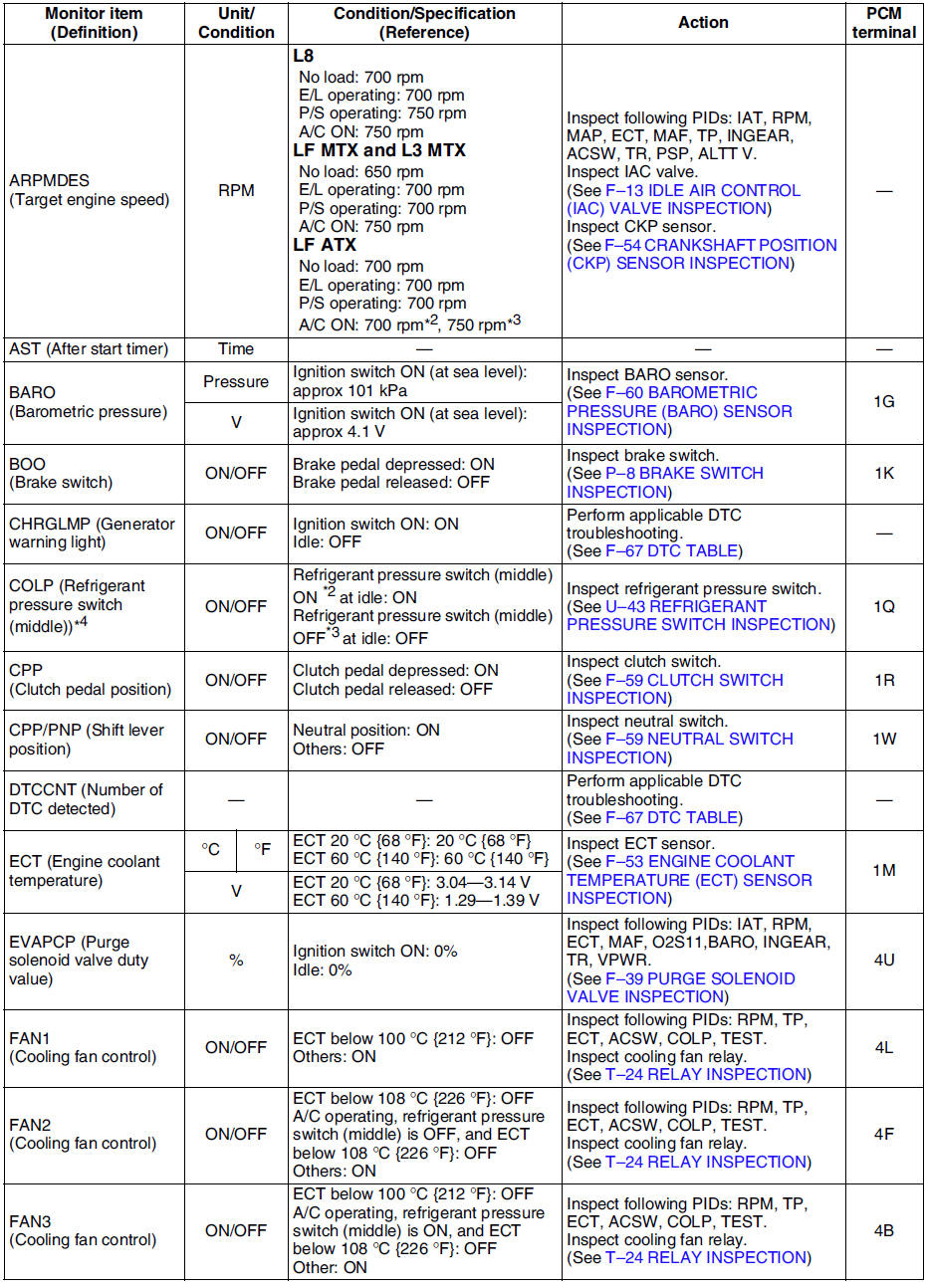
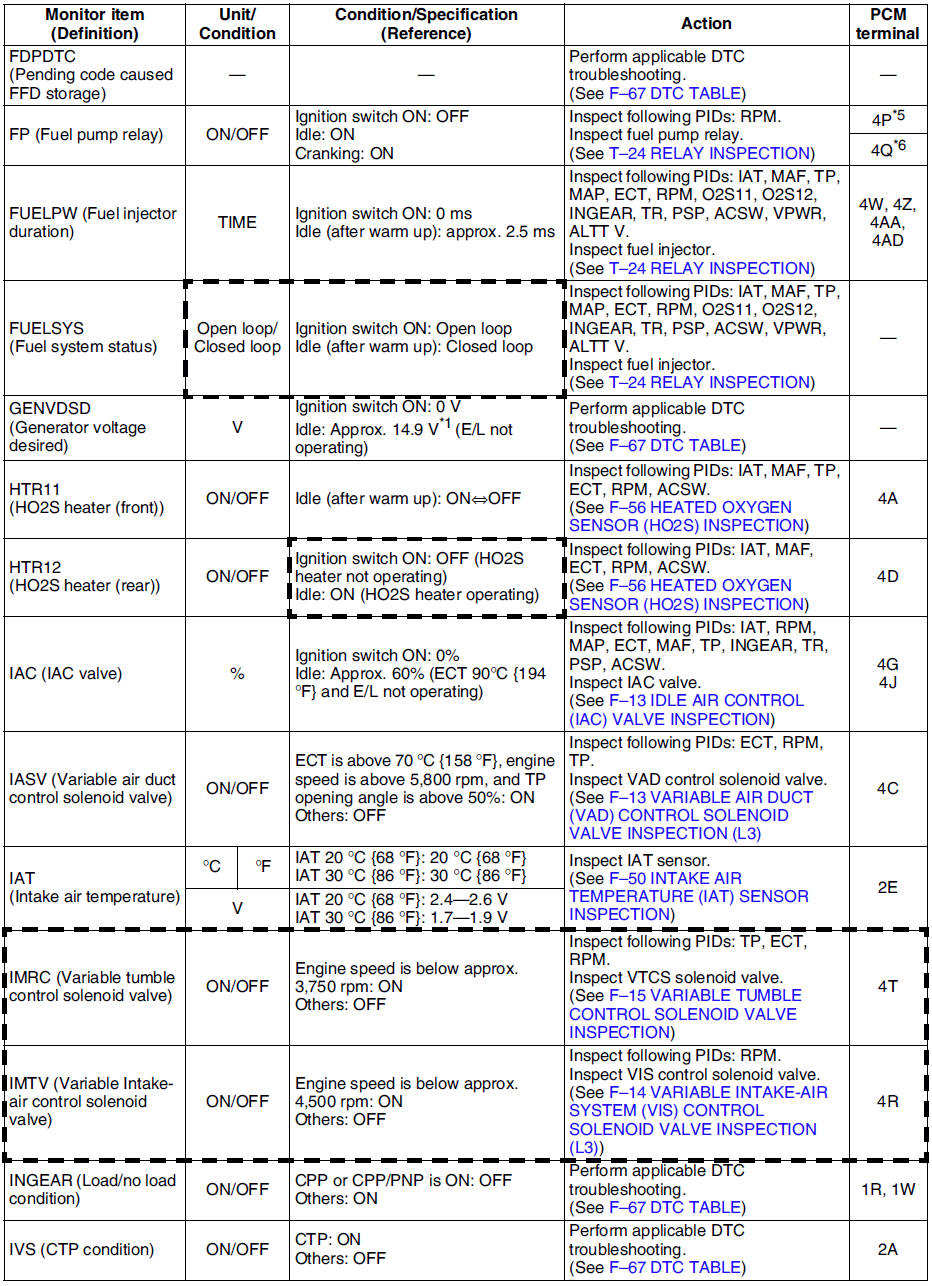
PID/DATA monitor table (reference)
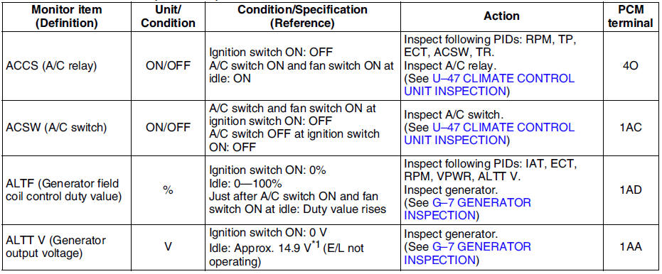
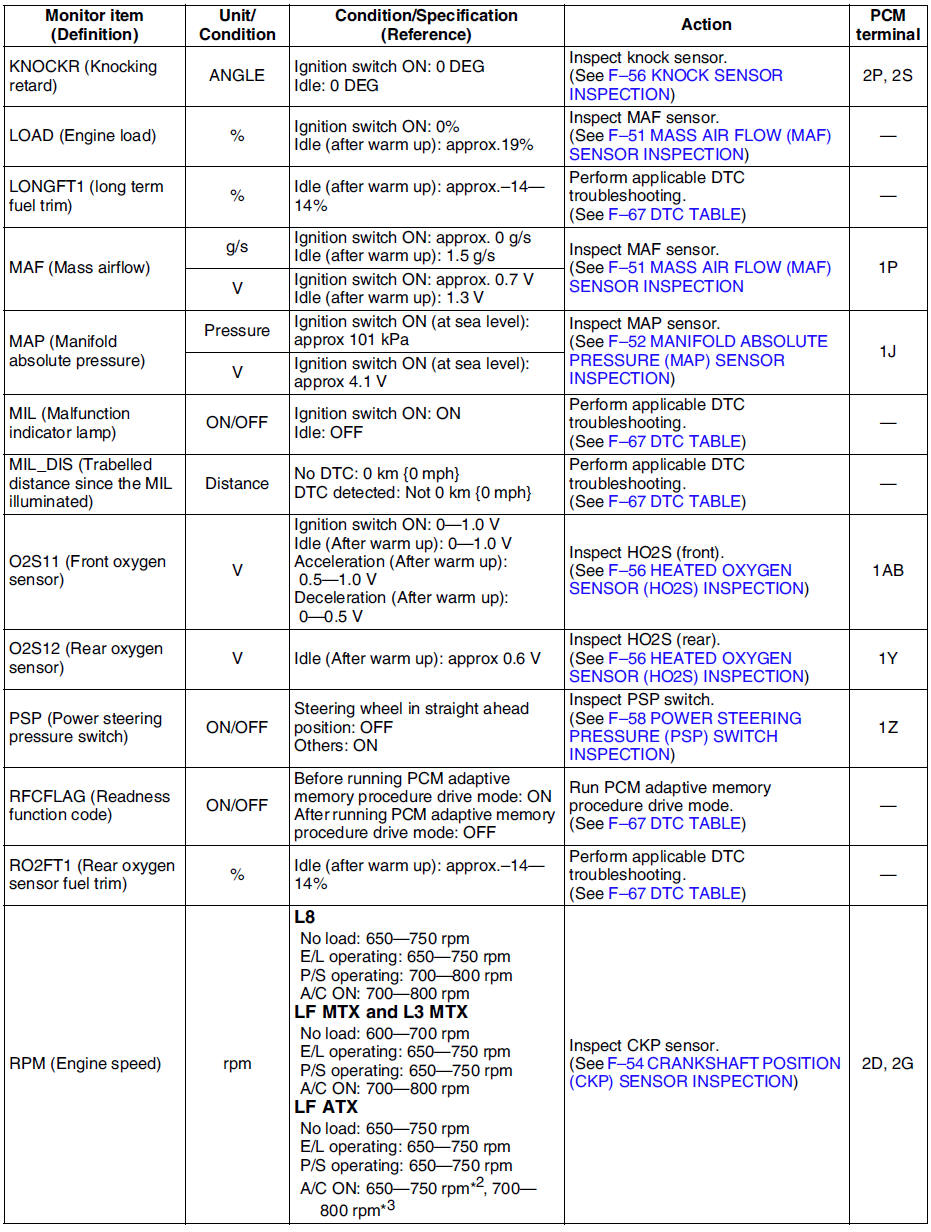
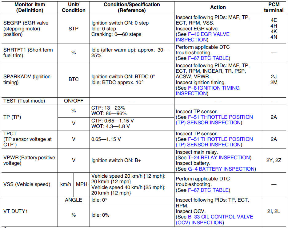
*1 : Calculated value; differs from terminal voltage
*2 : Refrigerant pressure switch (middle) turns on when the refrigerant pressure is 1.691.84 MPa {17.318.7 kgf/cm2, 247265 psi}
*3 : Refrigerant pressure switch (middle) turns off when the refrigerant pressure is 1.261.49 MPa {12.915.1 kgf/cm2, 184214 psi}
*4 : L3 and L8, LF (Intensely hot area) models
*5 : Immobilizer system equipped
*6 : Immobilizer system not equipped
- Following PIDs are for the ATX models. If inspects for following PIDs, see PID/DATA MONITOR INSPECTION.
PIDs for the ATX models
- GEAR
- LINEDES
- LPS
- OP_SW_B
- SSA/SS1
- SSB/SS2
- SSC/SS3
- TCS
- TFT
- TFTV
- THOP
- TR
- TR_SENS
- TSS
 Pcm removal/installation
Note
For replace the PCM, Setup the WDS and perform the PCM
configuration. (See PCM CONFIGURATION.)
1. Disconnect the negative battery cable.
2. For R.H.D, perform the following procedures. ...
 Pcm configuration
1. Connect the WDS to DLC-2.
2. Set up the WDS (including the vehicle recognition.)
3. Select Module programming.
4. Select Programmable module installation.
5. Select PCM and perform procedures ...
Other materials:
Mazda 6 Service Manual: Uniform Tire Quality Grading System (UTQGS)
This information relates to the tire grading system developed by the U.S. National
Highway Traffic Safety Administration for grading tires by tread wear, traction,
and temperature performance.
Tread Wear
The tread wear grade is a comparative rating based on the wear rate of the tire
when tes ...
Mazda 6 Service Manual: Air bleeding
1. Inspect the fluid level. (See POWER STEERING FLUID INSPECTION.)
2. Jack up the front of the vehicle and support it on safety stands.
3. Turn the steering wheel fully to the left and right several times with the
engine not running.
4. Reinspect the fluid level.
If it has dropped, add flui ...