Mazda 6 Service Manual: Procedures for determining the location of a malfunction
System Wiring Diadram
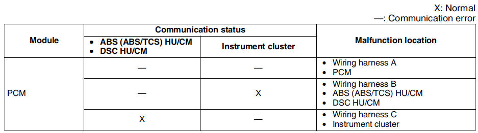
PCM
1. Check the display of DTC U0121 and/or U0155, using the SST
(WDS or equivalent). (See DTC TABLE.)
2. Referring to the following table, determine the malfunctioning part of the CAN system.
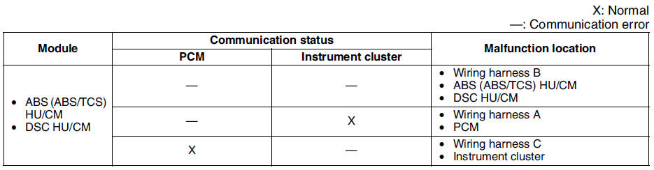
ABS/TCS HU/CM or DSC HU/CM
1. Accec and monitor the PCM MSG and IC MSGof PID using the SST
(WDS or equivalent).
2. Referring to the PID/DATA MONITOR, confirm the display status of the PID. (See PID/DATA MONITOR TABLE.)
3. Referring to the following table, determine the malfunctioning part of the CAN system.
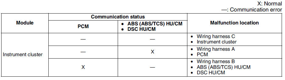
Instrument Cluster
1. Accec and monitor the PCM MSG and ABS MSG of PID using the SST
(WDS or equivalent).
2. Referring to the PID/DATA MONITOR, confirm the display status of the PID. (See PID/DATA MONITOR TABLE.)
3. Referring to the following table, determine the malfunctioning part of the CAN system.

 Dtc u0073, u1900, u2516
Diagnostic procedure
...
Other materials:
Mazda 6 Service Manual: Operating the Power Windows
NOTE
Each passenger window can be operated with each door switch when the
power window lock switch on the driver's door is in the unlocked position.
Each passenger window can also be operated using the master control switches
on the driver's door.
Normal opening/closing
To open the ...
Mazda 6 Service Manual: Clutch pedal adjustment
Clutch Pedal Height
Measure the distance from the upper surface of the pedal pad to the carpet.
If not as specified, adjust the pedal height by turning adjustment bolt
B and locknut A.
Pedal height(with carpet)
L.H.D.: 210-216 mm {8.27-8.50 in}
R.H.D.: 209-215 mm {8.23-8.46 in}
...