Mazda 6 Service Manual: Refrigerant lines removal/installation
1. Remove the battery.
2. Discharge the refrigerant from the system. (See RECOVERY.) (See CHARGING.)
3. Remove the washer tank. (L.H.D. only) (See WASHER TANK REMOVAL/INSTALLATION.)
4. Remove the air cleaner cover, air cleaner element and air cleaner case.
(See INTAKE-AIR SYSTEM
REMOVAL/INSTALLATION.)
5. Remove the charcoal canister.
6. Remove the No.3 engine mount. (L.H.D. only)
7. Remove the shroud panel. (See SHROUD PANEL REMOVAL/INSTALLATION.)
9. Remove the right splash shield.
10. Remove the right mud guard. (L.H.D. only)
Caution
- If moisture or foreign material enters the refrigeration cycle, cooling ability will be lowered and abnormal noise will occur. Always immediately plug all open fittings after removing any refrigeration cycle parts to keep moisture or foreign material out of the cycle.
10. Remove in the order indicated in the table. Do not allow compressor oil to spill.
11. Install in the reverse order of removal.
12. Perform the refrigerant system performance test. (See REFRIGERANT SYSTEM PERFORMANCE TEST.)
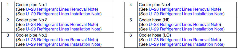
Refrigerant Lines Removal Note
Nut joint type
Loosen the nut using two spanners, then remove the cooler pipe or hose.
Block joint type
Disconnect the block joint type pipes by grasping female side of the block with pliers or similar tool and holding firmly, then remove the connection bolt or nut.
Spring-lock coupling type
1. Set the SST
.
2. While looking through the inspection hole of the SST
, insert the protruding part of the SST
until it makes contact with the cage section.
3. Use the SST
to disconnect the male pipe or hose from the female by pulling the male pipe or hose.
Note
- The male pipe or hose can be disconnected easily from the female pipe by pulling from the male pipe or hose while maintaining the pressure of the protruding part of the SST.
Refrigerant Lines Installation Note
1. When installing a new cooler pipe No.4 or cooler hose (LO), add a supplemental amount of ATMOS GU10 compressor oil into the refrigeration cycle.
Supplemental amount (approximate quantity) 5 ml {5 cc, 0.2 fl oz}: Cooler pipe No.4 10 ml {10 cc, 0.3 fl oz}: Cooler hose (LO)
2. Apply compressor oil to the O-rings and connect the joints.
3. Tighten the joints.
Nut or block joint type
1. Tighten the nut or bolt of joint by hand.
2. Tighten the joint to the specified torque. If it is a nut joint, tighten the nut with a spanner and torque wrench.
3. Connect the block joint type pipes by grasping the female side of the block with pliers or similar tool and holding firmly, then tighten the connection bolt or nut with a torque wrench.
Spring-lock coupling type
Connect the male pipe or hose by twisting it onto female pipe until the garter spring at the male pipe or hose is over the flared end of female pipe.
Note
- When the male pipe or hose is replaced, the indicator ring comes out after connecting to indicate that it is locked.
 Condenser inspection
1. Inspect for cracks, damage, and oil leakage.
If any are found, replace the condenser.
2. Inspect for fins clogged by dust.
If any are clogged, remove the dust from the fins.
3. Inspec ...
 Control system
...
Other materials:
Mazda 6 Service Manual: Removal/Installation
To remove the head restraint, pull it up while pressing the stop-catch.
To install the head restraint, insert the legs into the holes while pressing
the stop-catch.
WARNING
Always drive with the head restraints installed when seats are being used
and make sure they are properly installed: Dri ...
Mazda 6 Service Manual: Windshield wiper motor removal/installation
1. Disconnect the negative battery cable.
2. Remove the windshield wiper arm and blade. (See WINDSHIELD WIPER ARM AND
BLADE REMOVAL/INSTALLATION.)
3. Remove the cowl grille. (See COWL GRILLE REMOVAL/INSTALLATION.)
4. Remove in the order indicated in the table.
5. Install in the reverse ord ...