
Mazda 6 Service Manual: Compression pressure
COMPRESSION INSPECTION
Warning
- Hot engines and oil can cause severe burns. Be careful not to burn yourself during removal/installation of each component.
1. Verify that the battery is fully charged.
- Recharge it if necessary. (See BATTERY INSPECTION.)
2. Warm up the engine to the normal operating temperature.
3. Stop the engine and allow it to cool off for about 10 min.
4. Perform Fuel Line Safety Procedures. Leave the fuel pump relay removed.
(See BEFORE REPAIR
PROCEDURE.)
Warning
- Fuel vapor is hazardous. It can very easily ignite, causing serious injury and damage. Always keep sparks and flames away from fuel.
- Fuel line spills and leakage are dangerous. Fuel can ignite and cause serious injuries or death and damage. Fuel can also irritate skin and eyes. To prevent this, always complete the Fuel Line Safety Procedure. (See Fuel Line Safety Procedure.)
5. Remove the ignition coil connector.
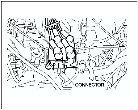
6. Remove the spark plugs. (See SPARK PLUG REMOVAL/INSTALLATION.)
7. Connect a compression gauge into the spark plug hole.
8. Fully depress the accelerator pedal and crank the engine.
9. Note the maximum gauge reading.
10. Inspect each cylinder as above.
- If the measured value is less than the limited value, or there is a
cylinder whose compression value varies from that of other cylinders by
196.1 kPa {1.999 kgf/cm2, 28.44 psi}
or more, add a small amount of engine oil through the spark plug hole. Then measure the compression pressure and perform the respective operations for the following cases.
- If the compression increases, the piston, the piston rings, or cylinder wall may be worn and overhaul is required.
- If the compression stays low, a valve may be stuck or improperly seated and overhaul is required.
- If the compression in adjacent cylinders stays low, the cylinder head gasket may be damaged or the cylinder head distorted and overhaul is required.
Compression
kPa {kgf/cm2, psi} [rpm]
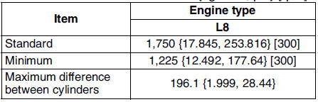
kPa {kgf/cm2, psi} [rpm]
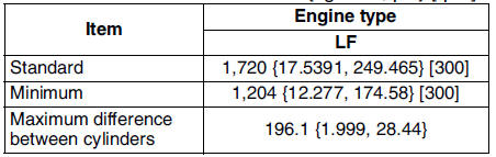
kPa {kgf/cm2, psi} [rpm]
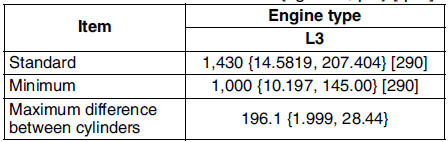
11. Disconnect the compression gauge.
12. Install the spark plugs. (See SPARK PLUG REMOVAL/INSTALLATION.)
13. Connect the ignition coil connector.
14. Install the fuel pump relay. (See BEFORE REPAIR PROCEDURE.)
 Valve clearance adjustment
1. Disconnect the negative battery cable.
2. Remove the tire (RH).
3. Remove the splash shield (RH).
4. Remove the spark plugs. (See SPARK PLUG REMOVAL/INSTALLATION.)
5. Remove the high-tension le ...
 Timing chain
TIMING CHAIN REMOVAL/INSTALLATION
Warning
Fuel vapor is hazardous. It can very easily ignite, causing
serious injury and damage. Always keep sparks and flames away from fuel.
Fuel line spill ...
Other materials:
Mazda 6 Service Manual: Dsc hu/cm inspection
1. Remove the battery and battery bracket.
2. Disconnect the DSC HU/CM connector.
3. Connect the SST (49 G066 004) to the DSC HU/CM connector and
harness side connector.
4. Inspect voltage referring the table below.
Terminal Voltage Table (reference value)
(Ignition switch is at ON, and conne ...
Mazda 6 Service Manual: Solenoid valve removal/installation
1. Disconnect the negative battery cable.
2. Remove the under cover.
3. Remove the control valve body. (See CONTROL VALVE BODY REMOVAL.)
4. Remove the solenoid valve(s).
5. Apply ATF to a new O-ring and install it on the solenoid valve.
6. Install the solenoid valve in the control valve body. ...