Mazda 6 Service Manual: Timing chain
TIMING CHAIN REMOVAL/INSTALLATION
Warning
- Fuel vapor is hazardous. It can very easily ignite, causing serious injury and damage. Always keep sparks and flames away from fuel.
- Fuel line spills and leakage are dangerous. Fuel can ignite and cause serious injures or death and damage. Fuel can also irritate skin and eyes. To prevent this, always complete the Fuel Line Safety Procedure. (See Fuel Line Safety Procedure.)
1. Disconnect the negative battery cable.
2. Remove the spark plugs. (See SPARK PLUG REMOVAL/INSTALLATION.)
3. Remove the tire (RH).
4. Remove the under cover.
5. Loosen the water pump pulley bolt and removal the drive belt. (See DRIVE BELT REPLACEMENT.)
6. Remove the CKP sensor. (See CRANKSHAFT POSITION (CKP) SENSOR REMOVAL/INSTALLATION.)
7. Drain the engine oil. (See ENGINE OIL REPLACEMENT.)
8. Remove the P/S oil pump with the oil hose still connected and position the P/S oil pump so that it is out of the way. (See POWER STEERING OIL PUMP REMOVAL/INSTALLATION.)
9. Remove the front drive shaft (RH) from the joint shaft. (See JOINT SHAFT REMOVAL/INSTALLATION.)
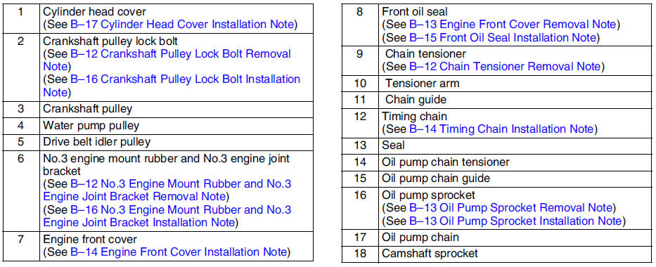
10. Remove in the order indicated in the table.
11. Install in the reverse order of removal.
12. Start the engine and:
- Inspect for the engine oil, engine coolant, transaxle oil and fuel leakage.
- Verify the ignition timing, idle speed and idle mixture. (See IGNITION TIMING INSPECTION.) (See IDLE MIXTURE INSPECTION.)
13. Perform a road test.
Crankshaft Pulley Lock Bolt Removal Note
1. Remove the cylinder block lower blind plug.
2. Install the SST
.
3. Turn the crankshaft clockwise the crankshaft is in the No.1 cylinder TDC position.
4. Hold the crankshaft pully by using the SSTs
.
Chain Tensioner Removal Note
1. Using a thin screwdriver, hold the chain tensioner ratchet lock mechanism away from the ratchet stem.
2. Slowly compress the tensioner piston.
3. Hold the tensioner piston using a 1.5 mm {0.059 in}
wire or paper clip.
No.3 Engine Mount Rubber and No.3 Engine Joint Bracket Removal Note
Suspend the engine using the SSTs
.
Oil Pump Sprocket Removal Note
Hold the oil pump sprocket by using the SST
.
Engine Front Cover Removal Note
Remove the oil seal using a screwdriver as shown.
Oil Pump Sprocket Installation Note
Hold the oil pump sprocket by using the SST
.
Timing Chain Installation Note
Install the SST
to the camshaft as shown.
European countries
Except European countries
2. Install the timing chain.
3. Remove the retaining wire or paper clip from the auto tensioner to apply tension to the timing chain.
Engine Front Cover Installation Note
1. Apply silicone sealant to the engine front cover as shown.
Caution
- Install the cylinder head cover within 10 minutes of applying the silicone sealant.
- Silicone sealant is not need in area C as indicated below due to an existing. (L3)
Thickness
A: 2.0-3.0 mm {0.079-0.118 in} B: 1.5-2.5 mm {0.059-0.098 in}
2. Install the cylinder head cover bolts in the order as shown.
Front Oil Seal Installation Note
1. Apply clean engine oil to the oil seal.
2. Push the oil seal slightly in by hand.
3. Compress the oil seal using the SST
and a hammer.
No.3 Engine Mount Rubber and No.3 Engine Joint Bracket Installation Note
1. Tighten the stud bolt of the No.3 engine mount bracket.
Tightening torque: 7.0-13 N·m {71.4-132.5 kgf·cm, 62.0-115.0 in·lbf}

2. Install the No.3 engine mount rubber hand-tighten.
3. Tighten the No.3 engine joint bracket is attached and bolts, nuts in the order shown.
Crankshaft Pulley Lock Bolt Installation Note
1. Install the SST
to the camshaft as shown.
European countries
Except European countries
2. Install the M6 x 1.0 bolt
in by hand.
3. Turn the crankshaft clockwise the crankshaft is in the No.1 cylinder TDC position.
4. Hold the crankshaft pully by using the SST
.
5. Tighten the crankshaft pulley lock bolt using the following two steps.
(1) Tighten to 96-104 N·m {9.8-10.6 kgf·m, 70.9-76.7 ft·lbf}
(2) Tighten 87°-93°
6. Remove the M6 x 1.0 bolt.
7. Remove the SST
from the camshaft.
8. Remove the SST
from the cylinder block lower blind plug.
9. Rotate the crankshaft clockwise two turns until the TDC position.
- If not aligned, loosen the crankshaft pulley lock bolt and repeat from Step 1.
10. Install the cylinder block lower blind plug.
Tightening torque: 18-22 N·m {1.9-2.2 kgf·m, 13.3-16.2 ft·lbf}
Cylinder Head Cover Installation Note
1. Apply silicone sealant to the mating faces as shown.
Caution
- Install the cylinder head cover within 10 minutes of applying the silicone sealant.
Dot diameter:
4.0-6.0 mm {0.16-0.23 in}
2. Install the cylinder head cover with a new gasket.
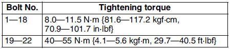
3. Tighten the bolts in the order shown.
Tightening torque: 8.0-11.5 N·m {81.6-122.3 kgf·cm, 70.9-106.2 in·lbf}
 Compression pressure
COMPRESSION INSPECTION
Warning
Hot engines and oil can cause severe burns. Be careful not to burn
yourself during removal/installation of each component.
1. Verify that the battery is fully ...
 Cylinder head gasket
CYLINDER HEAD GASKET REPLACEMENT
Warning
Fuel vapor is hazardous. It can very easily ignite, causing
serious injury and damage. Always keep sparks and flames away from fuel.
Fuel line spills ...
Other materials:
Mazda 6 Service Manual: Transmitter battery replacement
1. Insert a small screwdriver into the slot and gently pry open the
transmitter.
2. Press the portion of the battery indicated by A and remove the battery.
3. Install a new battery (CR2025) into the front portion of the holder with
the positive pole (+) facing up. Press on the B portion of ...
Mazda 6 Service Manual: Electrical parts
Battery cable
Before disconnecting connectors or removing electrical parts, disconnect
the negative battery cable.
Wiring Harness
To remove the wiring harness from the clip in the
engine room, pry up the hook of the clip using a
flathead screwdriver.
...