
Mazda 6 Service Manual: Connectors
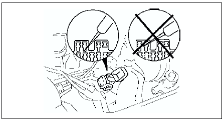
Data link connector
- Insert the probe into the terminal when connecting a jumper wire to the data link connector.
Caution
- Inserting a jumper wire probe into the data link connector terminal may damage the terminal.
Disconnecting connectors
- When disconnecting connector, grasp the connectors, not the wires.
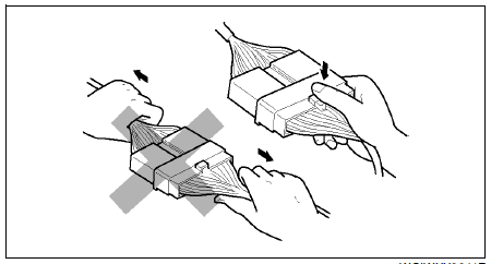
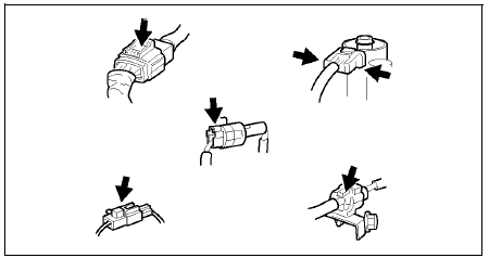
- Connectors can be disconnected by pressing or pulling the lock lever as shown.
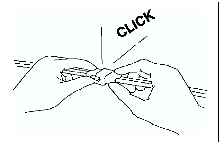
Locking connector
- When locking connectors, listen for a click indicating they are securely locked.
Inspection
- When a tester is used to inspect for continuity or measuring voltage, insert the tester probe from the wiring harness side.
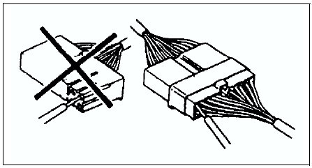
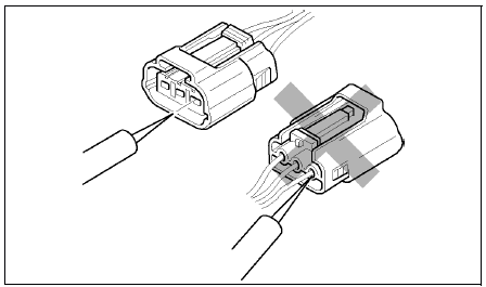
- Inspect the terminals of waterproof connectors from the connector side since they cannot be accessed from the wiring harness side.
Caution
- To prevent damage to the terminal, wrap a thin wire around the tester probe before inserting into terminal.
Terminals
Inspection
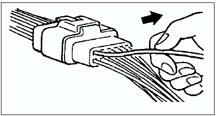
- Pull lightly on individual wires to verify that they are secured in the terminal.
Replacement
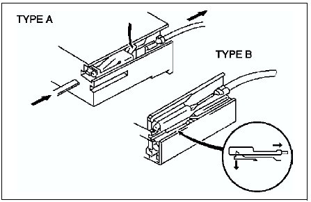
- Use the appropriate tools to remove a terminal as shown. When installing a terminal, be sure to insert it until it locks securely.
- Insert a thin piece of metal from the terminal side of the connector and with the terminal locking tab pressed down, pull the terminal out from the connector.
Sensors, Switches, and Relays
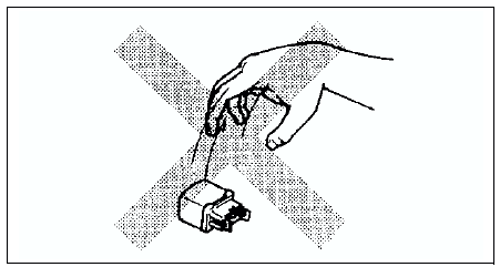
- Handle sensors, switches, and relays carefully. Do not drop them or strike them against other objects.
Wiring Harness
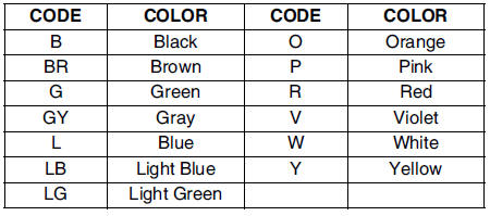
Wiring color codes
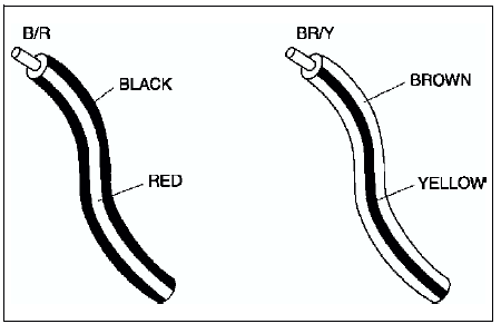
- Two-color wires are indicated by a two-color code symbol.
- The first letter indicates the base color of the wire and the second the color of the stripe.
Fuse
Replacement
- When replacing a fuse, be sure to replace it with one of the same capacity. If a fuse fails again, the circuit probably has a short and the wiring should be inspected.
- Be sure the negative battery terminal is disconnected before replacing a main fuse.
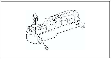
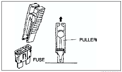
- When replacing a pullout fuse, use the fuse puller.
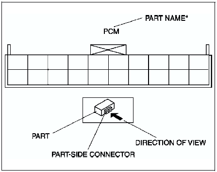
Direction of View for Connector
Part-side connector
Direction of view is from the terminal side.
* : Part names are shown only when there are multiple connector drawings.
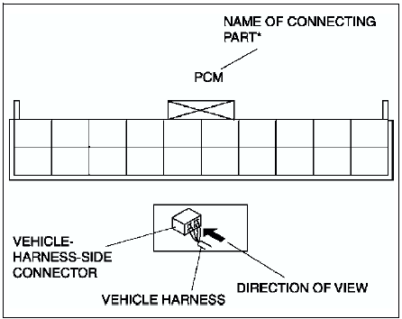
Vehicle-harness-side connector
Direction of view is from the harness side.
* : Part names are shown only when there are multiple connector drawings.
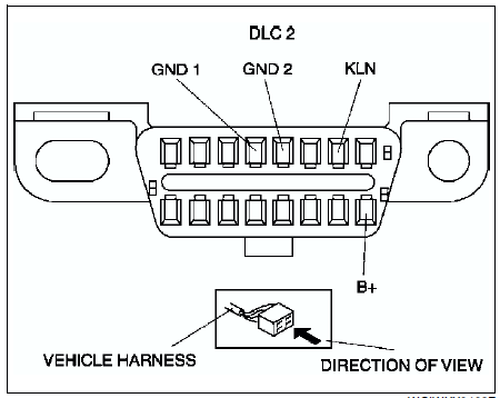
Other
Because vehicle-harness-side connectors, such as the DLC 2, have to be viewed from the terminal side, the direction of view is from the terminal side.
 Electrical parts
Battery cable
Before disconnecting connectors or removing electrical parts, disconnect
the negative battery cable.
Wiring Harness
To remove the wiring harness from the clip in the
en ...
 Electrical troubleshooting tools
Jumper wire
A jumper wire is used to create a temporary circuit. Connect the jumper
wire between the terminals of a circuit to bypass a switch.
Caution
Do not connect a jumper wire from ...
Other materials:
Mazda 6 Service Manual: Coming Home Light
The coming home light turns on the headlights (low beams) when the lever is operated.
To turn on the lights
When the lever is pulled with the ignition switched to ACC or OFF, the low beam
headlights turn on.
The headlights turn off after a certain period of time has elapsed after the
doors ar ...
Mazda 6 Service Manual: Headlight aiming
Low-beam
1. Set up a screen as shown in the figure below for aiming the headlights.
2. Adjust the tire air pressure to the specification.
3. Position the unloaded vehicle on a flat, level surface.
4. Seat one person in the driver's seat.
5. Position the vehicle straight ahead and perpendicu ...