
Mazda 6 Service Manual: Oil control valve (ocv) removal/installation
L3
1. Disconnect the negative battery cable.
2. Remove the plug hole plate.
3. Remove the high-tension lead. (See HIGH-TENSION LEAD REMOVAL/INSTALLATION.)
4. Remove the oil control valve (OCV) connector.
5. Remove the ventilation hose.
6. Remove the cylinder head cover. (See Cylinder Head Cover Installation Note.)
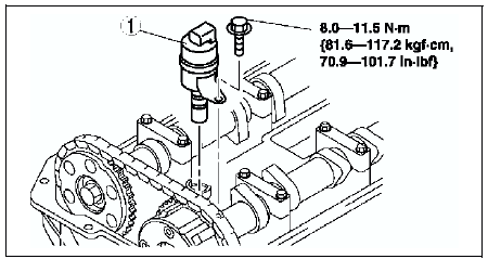
7. Remove in the order indicated in the table.
8. Install in the reverse order of removal.


 Oil control valve (ocv) inspection
L3
Coil Resistance Inspection
1. Disconnect the negative battery cable.
2. Disconnect the oil control valve connector.
3. Measure the resistance between terminals A and B using an ohmmeter.
If ...
Other materials:
Mazda 6 Service Manual: Scheduled Maintenance (Mexico)
Follow Schedule 1 if the vehicle is operated mainly where none of the following
conditions apply.
Repeated short-distance driving
Driving in dusty conditions
Driving with extended use of brakes
Driving in areas where salt or other corrosive materials are used
Driving on rough or muddy ...
Mazda 6 Service Manual: Fuse Panel Description
Fuse block (Engine compartment)
*Some models.
Fuse block (Left side)
*Some models. ...