Mazda 6 Service Manual: Technical data
ENGINE
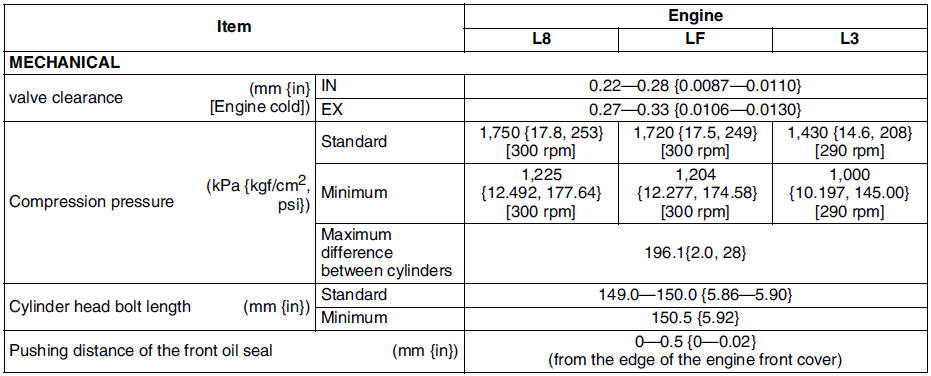
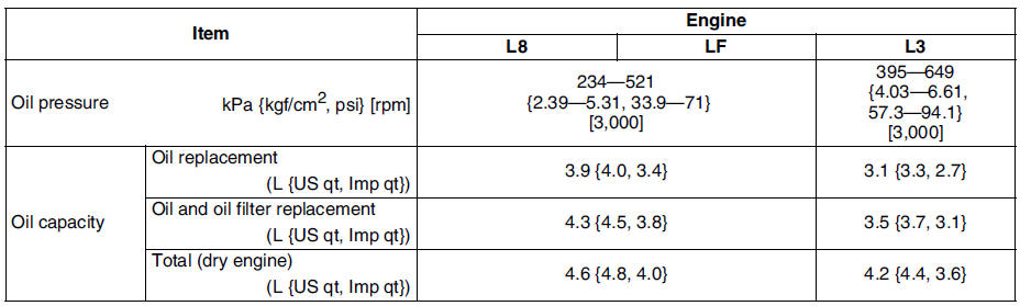
LUBRICATION SYSTEM
Note
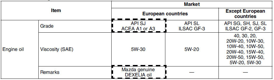
- The maintenance intervals on scheduled maintenance table (See SCHEDULED MAINTENANCE TABLE) can only be supported by the use of following oils.
Recommended engine oil
COOLING SYSTEM

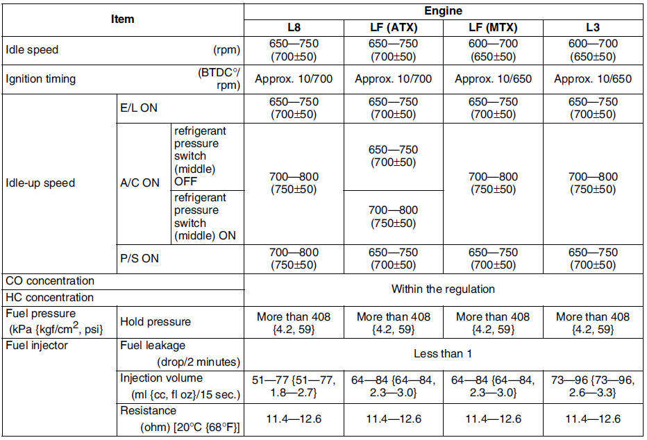
FUEL AND EMISSION CONTROL SYSTEMS
ENGINE ELECTRICAL SYSTEM
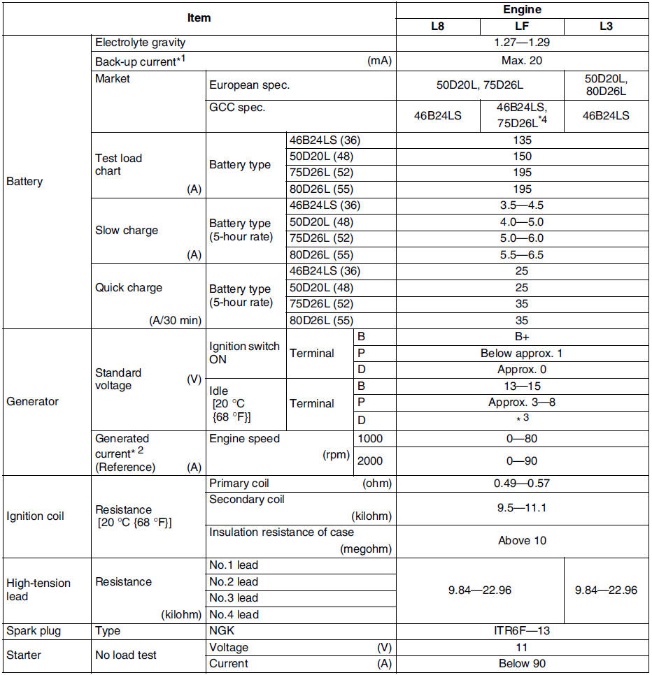
*1 : Back-up current is the constant flow of current present (for the audio unit, clock, PCM, etc.) when the ignition switch is off and with the ignition key removed.
*2 : Must not be 0 A.
*3 : Turn the following electrical loads on and verify that the voltage reading increases.
- Headlights, blower motor, and rear window defroster
*4 : Intensely hot area
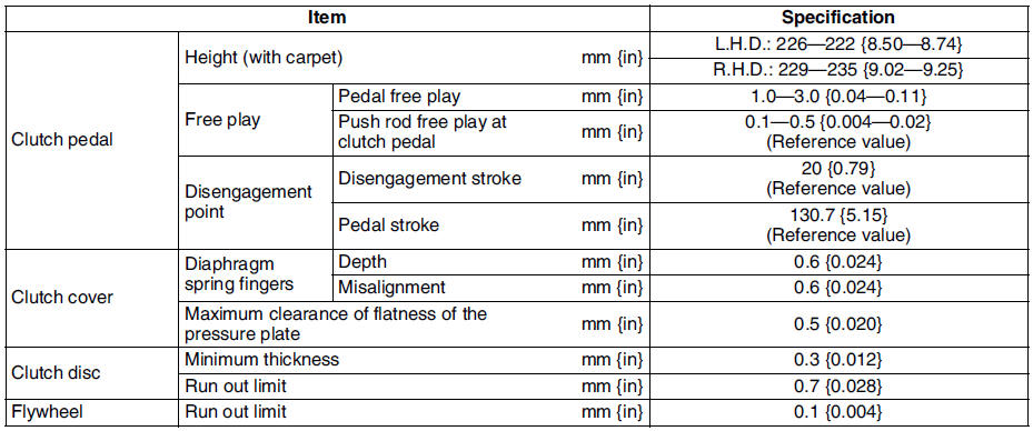
CLUTCH
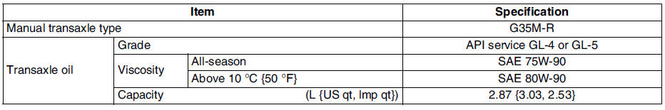
MANUAL TRANSAXLE
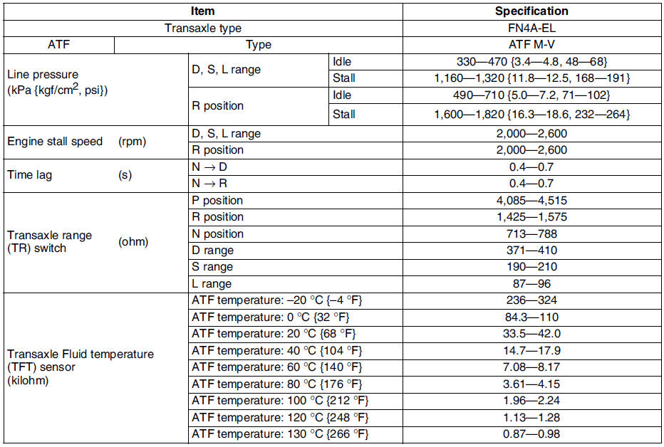
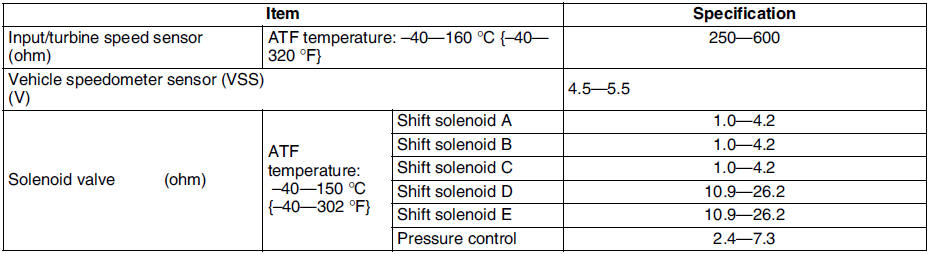
AUTOMATIC TRANSAXLE
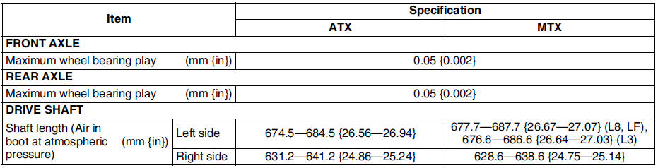
FRONT AND REAR AXLE
STEERING SYSTEM

* : When reservoir tank is at maximum volume
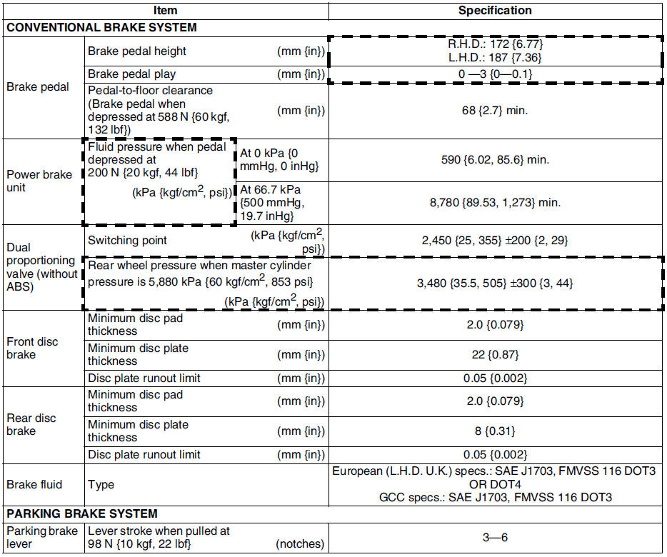
BRAKING SYSTEM
SUSPENSION
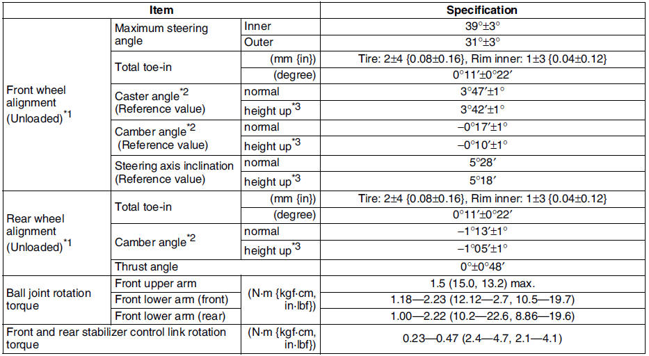
*1 : Fuel tank full. Engine coolant and engine oil are at specified level. Spare tire, jack, and tools are in designated position. Adjust to the median when carrying out wheel alignment.
*2 : Difference between left and right must not exceed 1° 30′.
*3 : Distance between wheel center and fender brim is following. Front: 402 mm {15.8 in} (reference value) Rear: 392 mm {15.4 in} (reference value)
Wheel and Tires
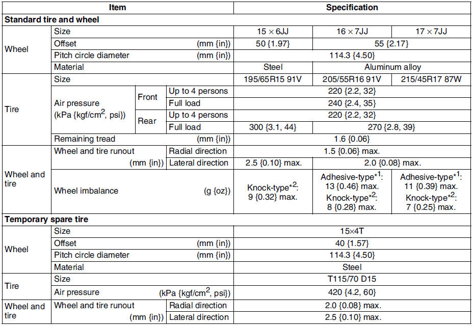
*1 : Total weight exceeds 160 g {5.65 oz}.
*2 : One balance weight: 60 g {2.12 oz} max. If the total weight exceeds 100 g {3.53 oz} on one side, rebalance after moving the tire around on the rim. Do not use 3 or more balance weights.
BODY ELECTRICAL SYSTEM
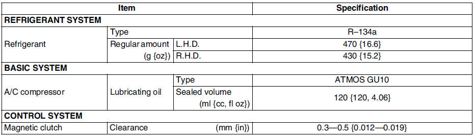
HEATER AND AIR CONDITIONER SYSTEMS
 No.9 noise while operating a/c system
Diagnostic procedure
* : If there is gas leakage, air enters into the A/C system. The desiccant
within the receiver/drier absorbs the moisture from the air and becomes
saturated. If the A/C ...
 Special tools
ENGINE
Ford SST numbers are collated with Mazda SST numbers in the example below.
Ford SSTs are marked with Ford SST number.
Example
1: Mazda SST number
2: Ford SST number
LUBRICATION SYSTEM ...
Other materials:
Mazda 6 Service Manual: Hold switch removal/installation
1. Disconnect the negative battery cable.
2. Remove the console.
3. Disconnect the connector and remove the HOLD switch terminals. (See
SELECTOR LEVER DISASSEMBLY/ASSEMBLY.)
4. Remove the selector lever knob component.
5. Remove the HOLD switch.
6. Install the HOLD switch to selector lever k ...
Mazda 6 Service Manual: Steering gear and linkage removal/installation
Caution
Performing the following procedures without first removing the ABS
wheel-speed sensor may possibly cause an open circuit in the harness if it
is pulled by mistake. Before performing the following procedures, remove the
ABS wheel-speed sensor (axle side) and fix it to an appropri ...