Mazda 6 Service Manual: Transaxle range (tr) switch adjustment
1. Disconnect the negative battery cable.
2. Remove the air cleaner component. (See INTAKE-AIR SYSTEM REMOVAL/INSTALLATION.)
Caution
- Water or foreign objects entering the connector can cause a poor connection or corrosion. Be sure not to drop water or foreign objects on the connector when disconnecting it.
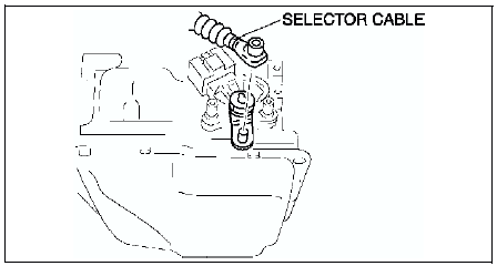
3. Remove the clip and disconnect the selector cable.
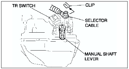
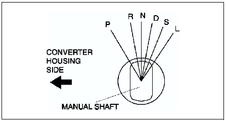
4. Rotate the manual shaft to the converter housing side fully, then return 2 notches to set the N position.
5. Disconnect the TR switch connector.
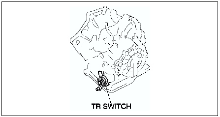
6. Loosen the TR switch mounting bolts.
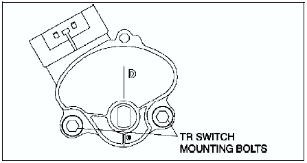
7. Measure the resistance between the terminals B and C.
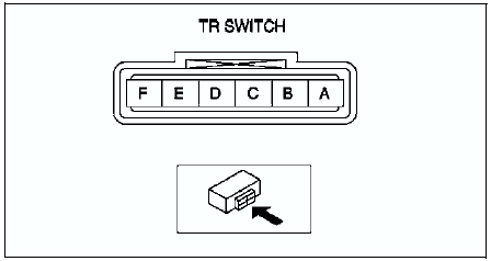
8. Adjust the switch to the point as follow.
- Resistance standard value 750 ohms
9. Tighten the TR switch mounting bolts.
Tightening torque 8-11 N·m {82-112 kgf·cm, 71-97 in·lbf}
10. Move the selector lever to N position.
11. Verify that the TR switch is aligned with N position.
12. Connect the TR switch connector.
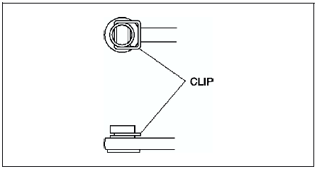
13. Install the clip to the selector cable as shown in the figure.
14. Connect the selector cable to the manual shaft lever as shown in the figure.
15. Inspect operation of the TR switch. (See TRANSAXLE RANGE (TR) SWITCH INSPECTION.)
- If not as specified, readjust the TR switch.
16. Install the air cleaner component. (See INTAKE-AIR SYSTEM REMOVAL/INSTALLATION.)
17. Connect the negative battery cable.
 Transaxle range (tr) switch removal/installation
1. Disconnect the negative battery cable.
2. Remove the air cleaner component. (See INTAKE-AIR SYSTEM
REMOVAL/INSTALLATION.)
Caution
Water or foreign objects entering the connector can cause a ...
 Transaxle fluid temperature (tft) sensor inspection
On-Vehicle Inspection
1. Disconnect the negative battery cable.
2. Remove the air cleaner component. (See INTAKE-AIR SYSTEM
REMOVAL/INSTALLATION.)
Caution
Water or foreign objects entering th ...
Other materials:
Mazda 6 Service Manual: Front Seat Belt Pretensioner and Load Limiting Systems
For optimum protection, the driver and front passenger seat belts are equipped
with pretensioner and load limiting systems. For both these systems to work properly
you must wear the seat belt properly.
Pretensioners:
When a collision is detected, the pretensioners deploy simultaneously with th ...
Mazda 6 Service Manual: Service procedure
Inspection, adjustment
Inspection and adjustment procedures are divided into steps. Important
points regarding the location and contents of the procedures are explained
in detail and shown in the illustrations.
Repair procedure
1. Most repair operations begin with an overview illustr ...
