Mazda 6 Service Manual: Abs (abs/tcs) hu/cm inspection
1. Disconnect the negative battery cable.
2. Connect the SST
between the ABS (ABS/TCS) HU/CM and harness connector with the ignition switch off.
3. Attach the tester leads to the SST
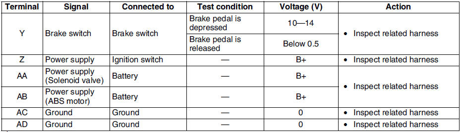
and inspect voltage referring the table below.
Terminal Voltage Table (Reference)
(Engine is idling, and connector is connected unless otherwise indicated.)

*1 : With TCS
*2 : Use this terminal at factory only, not used for inspection and repair at field
Inspection Using An Oscilloscope (Reference)
Wheel speed
- ABS/TCS HU/CM terminal:
RR : A ( + ) - B ( - )
LR : C ( + ) - F ( - )
RF : D ( + ) - G ( - )
LF : E ( + ) - I ( - )

- Oscilloscope setting:
1 V/DIV (Y), 2 ms/DIV (X), AC range
- Vehicle condition: Driving 30 km/h (18.6 mph)
Note
- As vehicle speed increases, period of wave shortens.
- If there is malfunctioning in the sensor rotor, wave profile warps.
Vehicle speed output
- ABS/TCS HU/CM terminal: V( + ) - AC ( - )

- Oscilloscope setting:
1 V/DIV (Y), 5 ms/DIV (X), DC range
- Vehicle condition: Driving 30 km/h (18.6 mph)
Note
- As vehicle speed increases, period of wave shortens.
 Abs (abs/tcs) or dsc hu/cm configuration
1. Connect the WDS or equivalent to the DLC-2.
2. Input vehicle information following the direction on the WDS or equivalent
screen.
3. Select Module programming.
4. Select Programmable module ...
 Tcs (dsc) off switch removal/installation
1. Press the hooks of the TCS OFF switch and pull the switch out.
2. Disconnect the connector.
3. Install in the reverse order of removal. ...
Other materials:
Mazda 6 Service Manual: Front lower arm (rear) inspection
1. Remove the lower arm (rear) from the vehicle.
2. Inspect for damage, cracks, and bending.
3. Inspect the ball joint rotation torque.
(1) Rotate the ball joint five times.
(2) Measure the rotation torque using a suitable allen socket and a
torque wrench.
If not within the specif ...
Mazda 6 Service Manual: Theft-deterrent control module inspection
1. Remove the theft-deterrent control module without disconnecting the
connectors.
2. Measure the voltage at the theft-deterrent control module terminals as
indicated below.
3. Disconnect the theft-deterrent control module connector before inspecting
for continuity at terminals L, Q, S, T, a ...