Mazda 6 Service Manual: Steering gear and linkage assembly
Caution
- Place copper plates, rag, or similar material in a vise, when secure the mounting bracket portion of the steering gear.
Assemble in the order indicated in the table.
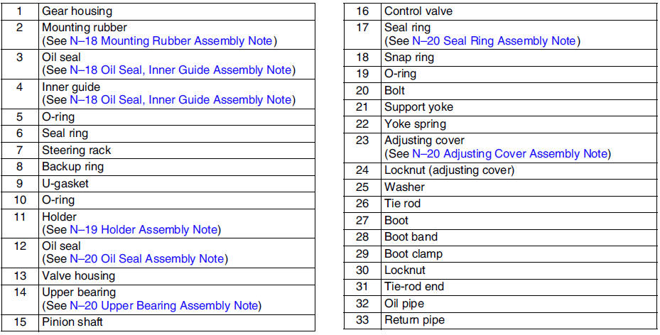
Mounting Rubber Assembly Note
1. Apply soapy water to the rubber part of the mounting rubber.
2. Press the mounting rubber until the mounting rubber end comes out completely from the gear housing using the SSTs
and a press.
3. Reverse the gear housing, then press the mounting rubber until the mounting rubber end comes out completely from the other side. At this time, mounting rubber end and steel pipe are aligned.
Oil Seal, Inner Guide Assembly Note
1. Install a new O-ring and a new seal ring to the racks piston.
2. After installing the seal ring, seat it properly at the piston circumference.
3. Apply grease to a new oil seal and inner guide.
4. Install the oil seal to the SST
.
5. Using the SST
, place the oil seal and inner guide at the edge of the steering racks pinion, and remove the SST
.
6. After installing the steering rack to the gear housing, press the oil seal and inner guide using the SSTs
until the force required suddenly increases.
Holder Assembly Note
1. Apply grease to the U-gasket and O-ring.
2. Assemble the U-gasket, backup ring and O-ring into the holder.
3. Assemble the SST
to the steering rack.
4. Stake the holder to the cylinder using a punch.
Oil Seal Assembly Note
1. Apply grease to a new oil seal.
2. Press in the new oil seal using the SSTs
.
Upper Bearing Assembly Note
1. Apply grease to a new upper bearing.
2. Press in the upper bearing using the SST
.
Seal Ring Assembly Note
1. Install a new seal ring to the valve part of the pinion shaft using the SST
.
2. After installing it, seat it properly using the SST
.
3. Install the snap ring.
Adjusting Cover Assembly Note
1. Set the rack to the center position.
2. Tighten the adjusting cover to 4.9 N·m {50 kgf·cm, 36 in·lbf}
three times, then return it 25°
using the SST
.
3. Apply sealant to the threads of the locknut.
4. Attach the locknut.
5. Measure the pinion torque using the SST
and a pull scale.
Standard
Center of rack ±90°
0.8-1.2 N·m
{8.2-12.2 kgf·cm, 5.8-8.8 in·lbf} [Pull scale reading
8-12 N {0.9-1.2 kgf, 1.8-2.6 lbf}]Except center of rack ±90° Less than 1.6 N·m
{16.3 kgf·cm, 11.8 in·lbf} [Pull scale reading
Less than 16.7 N {1.7 kgf, 3.8 lbf}]
6. If not as specified, repeat steps 2 through 5.
7. Install the locknut using the SST
(49 B032 320).
Tightening torque 40-49 N·m {4.1-4.9 kgf·m, 30-36 ft·lbf}
Hermetic sealing inspection
1. Connect the SSTs
to the power cylinder section of the gear housing.
2. Apply 53.3 kPa {400 mmHg, 15.7 inHg}
vacuum with a vacuum pump and verify that it is held for at least 30 seconds.
3. If the vacuum is not held, replace the oil seal.

 Steering gear and linkage inspection
Rack Inspection
1. Inspect the rack for cracking, damage, and tooth wear. Replace it as
necessary.
2. Measure the runout of the rack.
Runout
Near point A: 0.15 mm {0.006 in} max.
Near po ...
 Power steering oil pump removal/installation
1. Remove in the order indicated in the table.
2. Install in the reverse order of removal.
...
Other materials:
Mazda 6 Service Manual: Variable valve timing actuator removal/installation
L3
Caution
Variable valve timing actuator can not be disassembled because it
is a precision unit.
Note
Variable valve timing actuator camshaft sprocket is integrated
with the variable valve timing actuator and cannot be disassembled.
1. Follow the timing chain removal/installati ...
Mazda 6 Service Manual: Master cylinder disassembly/assembly
Caution
If the master cylinder body is damaged, replace the unit as a
component. When securing the master cylinder in a vise, tighten only the
flange of the master cylinder.
1. Disassemble in the order indicated in the table.
2. Assemble in the reverse order of disassembly.
Stop ...