Mazda 6 Service Manual: Transaxle range (tr) switch removal/installation
1. Disconnect the negative battery cable.
2. Remove the air cleaner component. (See INTAKE-AIR SYSTEM REMOVAL/INSTALLATION.)
Caution
- Water or foreign objects entering the connector can cause a poor connection or corrosion. Be sure not to drop water or foreign objects on the connector when disconnecting it.
3. Disconnect the TR switch connector.
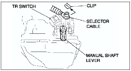
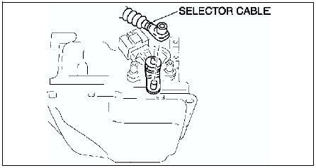
4. Remove the clip and disconnect the selector cable.
Caution
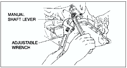
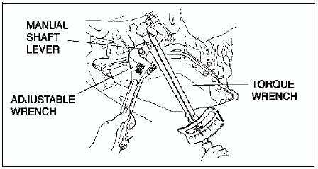
- Do not use an impact wrench. Hold the manual shaft lever when removing the manual shaft nut, or the transaxle may be damaged.
5. Set the adjustable wrench as shown to hold the manual shaft lever.
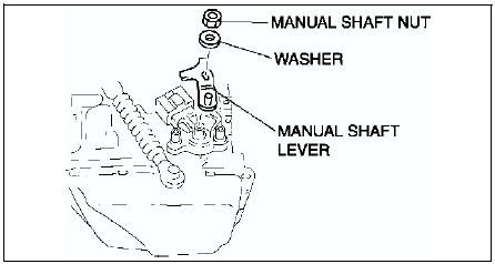
6. Remove the manual shaft nut and washer.
7. Remove the manual shaft lever.

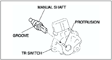
8. Remove the TR switch.
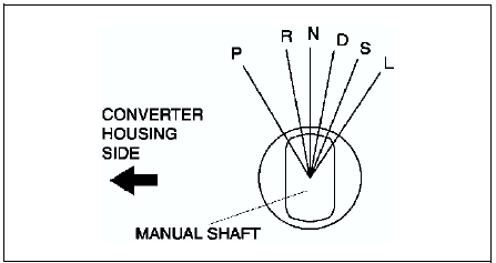
9. Rotate the manual shaft to the converter housing side fully, then return 2 notches to set the N position.
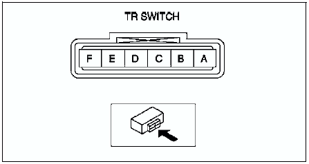
10. Turn the protrusion at resistance between the terminals B and C become 750 ohms.
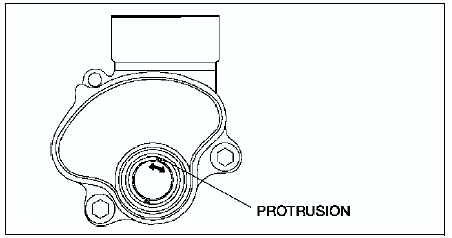

11. Install the TR switch while aligning the protrusion and groove as shown.
12. Hand-tighten the TR switch mounting bolts.
13. Inspect the resistance between the terminals B and C.
- If not as specified, readjust the TR switch. (See TRANSAXLE RANGE (TR) SWITCH ADJUSTMENT.)
Resistance
750 ohms
14. Tighten the TR switch mounting bolts.
Tightening torque 8-11 N·m {82-112 kgf·cm, 71-97 in·lbf}
Caution
- Do not use an impact wrench. Hold the manual shaft lever when removing the manual shaft nut, or the transaxle may be damaged.
15. Install the manual shaft lever and the washer.
16. Set the adjustable wrench as shown to hold the manual shaft lever, and tighten the manual shaft nut.
Tightening torque 32-46 N·m {3.2-4.7 kgf·m, 24-33 ft·lbf}
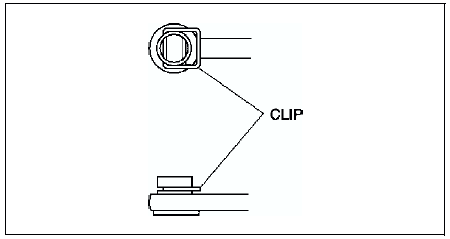
17. Install the clip to the SELECTOR CABLE as shown in the figure.
18. Shift the selector lever to P position.
19. Turn the manual shaft lever to P position.
20. Connect the selector cable.
21. Inspect for continuity at the TR switch. (See TRANSAXLE RANGE (TR) SWITCH INSPECTION.)
- If not as specified, readjust the TR switch. (See TRANSAXLE RANGE (TR) SWITCH ADJUSTMENT.)
22. Connect the TR switch connector.
23. Install the aircleaner component. (See INTAKE-AIR SYSTEM REMOVAL/INSTALLATION.)
24. Connect the negative battery cable.
25. Inspect operation of the TR switch. (See TRANSAXLE RANGE (TR) SWITCH INSPECTION.)
- If not as specified, readjust the TR switch. (See TRANSAXLE RANGE (TR) SWITCH ADJUSTMENT.)
 Transaxle range (tr) switch inspection
Operating Inspection
1. Verify that the starter operates only when the ignition switch is at the
START position with the selector lever in P or N position.
If not as specified, adjust the TR sw ...
 Transaxle range (tr) switch adjustment
1. Disconnect the negative battery cable.
2. Remove the air cleaner component. (See INTAKE-AIR SYSTEM
REMOVAL/INSTALLATION.)
Caution
Water or foreign objects entering the connector can cause a ...
Other materials:
Mazda 6 Service Manual: Wiper Blades
CAUTION
Hot waxes applied by automatic car washers have been known to affect
the wiper's ability to clean windows.
To prevent damage to the wiper blades, do not use gasoline, kerosene,
paint thinner, or other solvents on or near them.
When the wiper lever is in the AUTO position and th ...
Mazda 6 Service Manual: Relay inspection
Relay Type
Four-terminal
Type A
1. Remove the relay.
2. Inspect for continuity between the relay terminals using an ohmmeter.
If not as specified, replace the relay.
Type B
1. Remove the relay.
2. Inspect for continuity between the relay terminals using an ohmmeter.
If not as ...