
Mazda 6 Service Manual: Abs (abs/tcs) hu/cm removal/installation
Caution
- When replacing the ABS (ABS/TCS) HU/CM, configuration procedure must be done before removing the ABS (ABS/TCS) HU/CM. If configuration is not completed before removing the ABS (ABS/TCS) HU/CM, TCS will not work properly (with TCS model).
- Do not drop the ABS (ABS/TCS) HU/CM. Replace it if it is subjected to an impact.
1. Configurate the ABS (ABS/TCS) HU/CM (when only replacing it). (See ABS (ABS/TCS) or DSC HU/CM CONFIGURATION.)
2. Remove the battery, battery tray and battery tray bracket. (See BATTERY REMOVAL/INSTALLATION.)
3. Remove the under cover.
4. Remove in the order indicated in the table.
5. Install in the reverse order of removal.
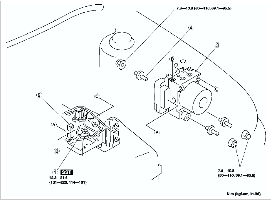

Connector Removal Note
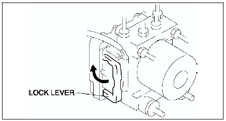
1. Pull the lock lever up and make it unlock.
2. Remove the connector.
ABS HU/CM Removal/Installation Note
When removing/installing the ABS HU/CM from/to the vehicle, attach a strip of protective tape on the ABS HU/CM connector to prevent brake fluid from entering.
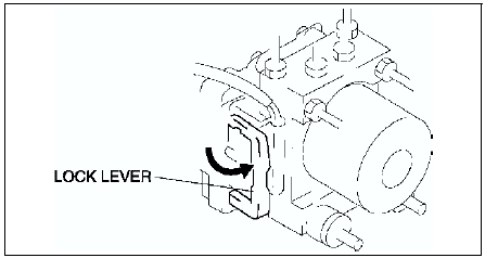
Connector Installation Note
Verify that the lock lever of the harness connector is completely pulled up.
 Abs (abs/tcs) hu/cm system inspection
System Inspection
Preparation
1. Verify that the battery is fully charged. With the ignition switch on,
verify that the ABS and BRAKE system warning lights goes out after 2.4
seconds.
2. If the ...
 Abs (abs/tcs) or dsc hu/cm configuration
1. Connect the WDS or equivalent to the DLC-2.
2. Input vehicle information following the direction on the WDS or equivalent
screen.
3. Select Module programming.
4. Select Programmable module ...
Other materials:
Mazda 6 Service Manual: Pre-delivery inspection
PRE-DELIVERY INSPECTION TABLE EXTERIOR
INSPECT and ADJUST, if necessary, the following items to
specification:
- Glass, exterior bright metal and paint for damage
- All weatherstrips for damage or detachment
- Door operation and alignment including side door and back door
- Wheel lug nu ...
Mazda 6 Service Manual: Foreword
Outline
There are two on-board diagnostic functions: Operation mode, which
inspects for and indicates correct operation of the input signals to the
control module, and condition detection mode, which indicates troubles in
the system.
The two functions can be done using either of the f ...