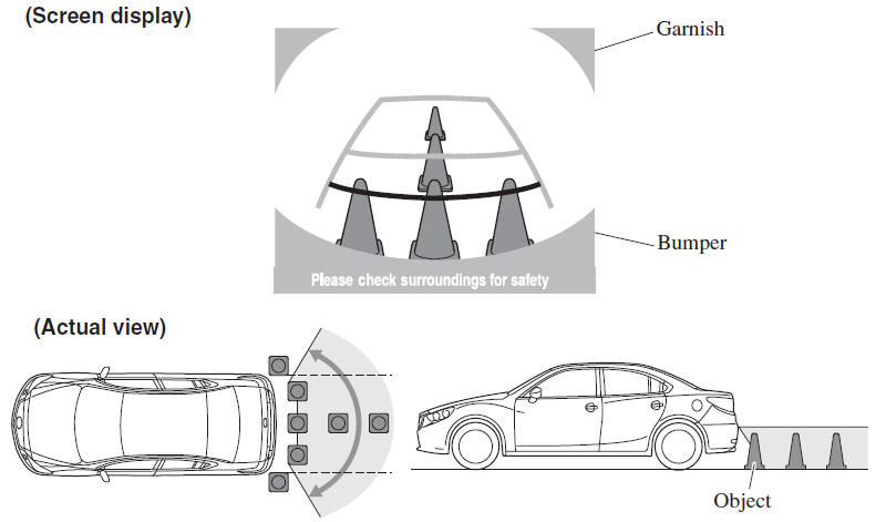
Mazda 6 Owners Manual: Displayable Range on the Screen
The images on the screen may be different from the actual conditions.
NOTE
- The displayable range varies depending on the vehicle and road conditions.
- The displayable range is limited. Objects under the bumper or around the bumper ends cannot be displayed.
- The distance appearing in the displayed image is different from the actual distance because the rear view parking camera is equipped with a specific lens.
- Some optionally installed vehicle accessories may be picked up by the camera. Do not install any optional parts that can interfere with the camera view, such as illuminating parts or parts made of reflective material.
- It may be difficult to see the display under the following conditions,
however, it does not indicate a malfunction.
- In darkened areas.
- When the temperature around the lens is high/low.
- When the camera is wet such as on a rainy day or during periods of high humidity.
- When foreign material such as mud is stuck around the camera.
- When the camera lens reflects sunlight or headlight beams.
- Image display may be delayed if the temperature around the camera is low.
 Switching to the Rear View Monitor Display
Shift the shift lever to R with the ignition switched ON to switch the display
to the rear view monitor display.
NOTE
When the shift lever is shifted from R to another shift lever position, the
...
 Viewing the Display
Guide lines which indicate the width of the vehicle (yellow) are displayed on
the screen as a reference to the approximate width of the vehicle in comparison
to the width of the parking space you ...
Other materials:
Mazda 6 Owners Manual: Antilock Brake System (ABS)
The ABS control unit continuously monitors the speed of each wheel. If one wheel
is about to lock up, the ABS responds by automatically releasing and reapplying
that wheel's brake.
The driver will feel a slight vibration in the brake pedal and may hear a chattering
noise from the brake system ...
Mazda 6 Owners Manual: Changing a Flat Tire
NOTE
If the following occurs while driving, it could indicate a flat tire.
Steering becomes difficult.
The vehicle begins to vibrate excessively.
The vehicle pulls in one direction.
If you have a flat tire, drive slowly to a level spot that is well off the road
and out of the way of tr ...