
Mazda 6 Service Manual: Dsc hu/cm removal/installation
Caution
- When replacing the DSC HU/CM, configuration procedure must be done before removing the DSC HU/CM. If configuration is not completed before removing the DSC HU/CM, DTC B2477 will be detected.
- Do not drop the DSC HU/CM. Replace it if it is subjected to an impact.
1. Configurate the DSC HU/CM (when only replacing it).(See ABS (ABS/TCS) or DSC HU/CM CONFIGURATION.)
2. Remove the battery, battery tray and battery tray bracket.(See BATTERY REMOVAL/INSTALLATION.)
3. Remove the under cover.
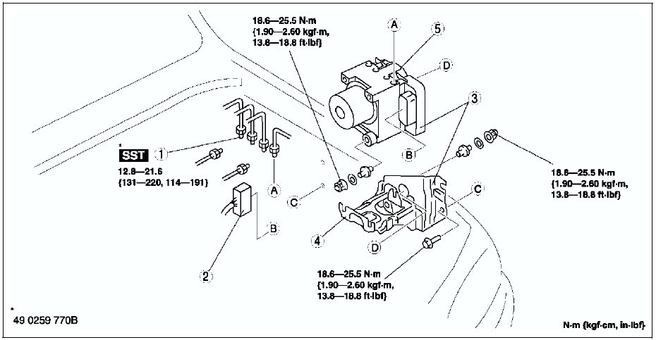
4. Remove in the order indicated in the table.
5. Install in the reverse order of removal.

Connector Removal Note
1. Rotate the lock lever 40° to the direction A, then push the lock lever to the direction B.
Caution
- After rotated the lever 40° , do not push the lock lever to the direction C. The lock lever will be damaged.
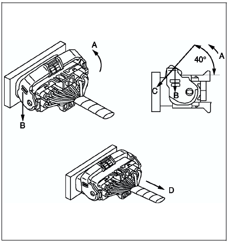
2. Verify that the lock lever is completely returned.
3. Remove the harness side connector to the direction D.
DSC HU/CM and Bracket Removal/Installation Note
When removing/installing the DSC HU/CM from/to the vehicle, attach a strip of tape on the DSC HU/CM connector to prevent brake fluid from entering.
Connector Installation Note
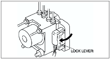
1. Verify that the connection part and waterproof packing are free of foreign material, then connect the connector.
2. Verify that the lock lever is completely pushed in.
 Dsc system inspection
Preparation
1. Verify that the battery is fully charged.
2. With ignition switch on, verify that the ABS warning light goes out after
2.4 seconds.
3. Turn the ignition switch off.
4. On level gro ...
 Dsc hu/cm inspection
1. Remove the battery and battery bracket.
2. Disconnect the DSC HU/CM connector.
3. Connect the SST (49 G066 004) to the DSC HU/CM connector and
harness side connector.
4. Inspect voltage referr ...
Other materials:
Mazda 6 Service Manual: STEP 3: Contact Better Business Bureau (BBB)
Mazda North American Operations realizes that mutual agreement on some issues
may not be possible. As a final step to ensure that your concerns are being fairly
considered, Mazda North American Operations has agreed to participate in a dispute
settlement program administered by the Better Busi ...
Mazda 6 Service Manual: Automatic transaxle fluid (atf) inspection
Automatic Transaxle Fluid (ATF) Condition Inspection
One way of determining whether the transaxle should be disassembled is by
noting:
If the ATF is muddy or varnished.
If the ATF smells strange or unusual.
ATF Condition
Automatic Transaxle Fluid (ATF) Level Inspection
Caution
Th ...