Mazda 6 Service Manual: Dsc hu/cm inspection
1. Remove the battery and battery bracket.
2. Disconnect the DSC HU/CM connector.
3. Connect the SST
(49 G066 004) to the DSC HU/CM connector and harness side connector.
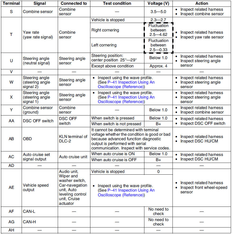
4. Inspect voltage referring the table below.
Terminal Voltage Table (reference value)
(Ignition switch is at ON, and connector is connected unless indicated otherwise.)
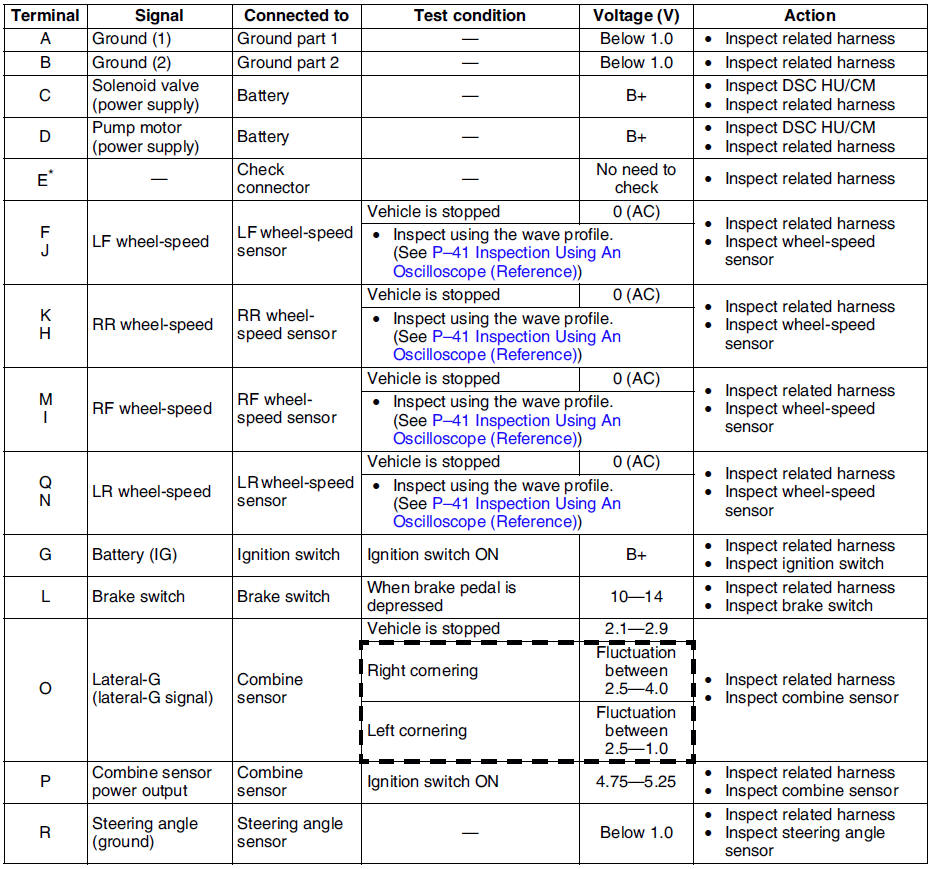
* : Used for vehicle manufacturing, not used for DSC.
Inspection Using An Oscilloscope (Reference)
Steering angle (steering angle signal 1 and 2)
- DSC HU/CM terminal:
Steering angle signal 2 : W ( + ) - R ( - )
Steering angle signal 1 : X ( + ) - R ( - )
- Oscilloscope setting:
1 V/DIV (Y), 25 ms/DIV (X), DC range
- Vehicle condition: Rotating steering wheel at one revolution per second
Note
- As steering wheel rotation speed increases, period of wave shortens.
- As for shape of steering angle signals 1 and 2, the phase is different.
Wheel speed
- DSC HU/CM terminal:
RF : M ( + ) - I ( - )
RR : K ( + ) - H ( - )
LF : F ( + ) - J ( - )
LR : Q ( + ) - N ( - )
- Oscilloscope setting:
1 V/DIV (Y), 2 ms/DIV (X), AC range
- Vehicle condition: Driving 30 km/h (18.6 mph)
Note
- As vehicle speed increases, period of wave shortens.
- If there is malfunctioning in the sensor rotor, wave profile warps.
Vehicle speed output
- DSC HU/CM terminal: AE ( + ) - A( - )
- Oscilloscope setting:
1 V/DIV (Y), 5 ms/DIV (X), DC range
- Vehicle condition: Driving 30 km/h (18.6 mph)
Note
- As vehicle speed increases, period of wave shortens.
 Dsc hu/cm removal/installation
Caution
When replacing the DSC HU/CM, configuration procedure must be done
before removing the DSC HU/CM. If configuration is not completed before
removing the DSC HU/CM, DTC B2477 will be d ...
 Combine sensor removal/installation
Caution
Be careful and do not allow the combine sensor to fall. If by
chance it is subjected to strong impact, replace it.
1. Remove the center console.
2. Remove in the order indicated in ...
Other materials:
Mazda 6 Service Manual: Clutch pedal adjustment
Clutch Pedal Height
Measure the distance from the upper surface of the pedal pad to the carpet.
If not as specified, adjust the pedal height by turning adjustment bolt
B and locknut A.
Pedal height(with carpet)
L.H.D.: 210-216 mm {8.27-8.50 in}
R.H.D.: 209-215 mm {8.23-8.46 in}
...
Mazda 6 Service Manual: Inspecting Engine Oil Level
1. Be sure the vehicle is on a level surface.
2. Warm up the engine to normal operating temperature.
3. Turn it off and wait at least 5 minutes for the oil to return to the oil pan.
4. Pull out the dipstick, wipe it clean, and reinsert it fully.
5. Pull it out again and examine the level.
The ...