Mazda 6 Service Manual: Front shock absorber and spring removal/installation
Caution
- Performing the following procedures without first removing the ABS wheel-speed sensor may possibly cause an open circuit in the harness if it is pulled by mistake. Before performing the following procedures, remove the ABS wheel-sensor (axle side) and fix it to an appropriate place where the sensor will not be pulled by mistake while servicing the vehicle.
1. Remove in the order indicated in the table.
2. Install in the reverse order of removal.
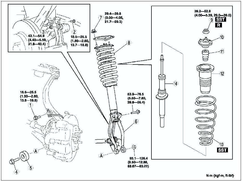
Bolt (Front Shock Absorber Lower Side) Removal Note
Support the knuckle with a jack to prevent from falling.
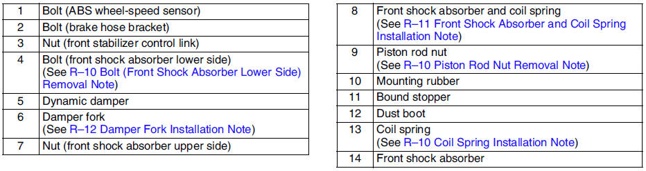
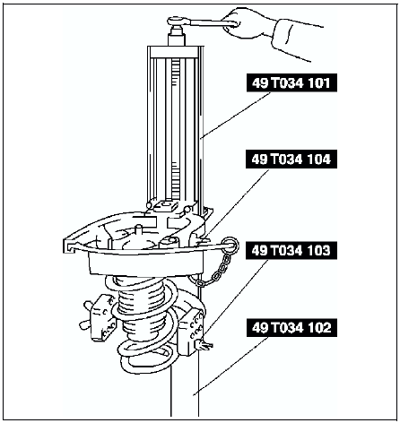
Piston Rod Nut Removal Note
Warning
- Removing the piston rod nut is dangerous. The shock absorber and spring could fly off under tremendous pressure and cause serious injury or death. Secure the shock absorber in the SSTs before removing the piston rod nut.
1. Protect the coil spring using a piece of cloth, then set the SSTs
.
2. Compress the coil spring using the SSTs
, and remove the piston rod nut.
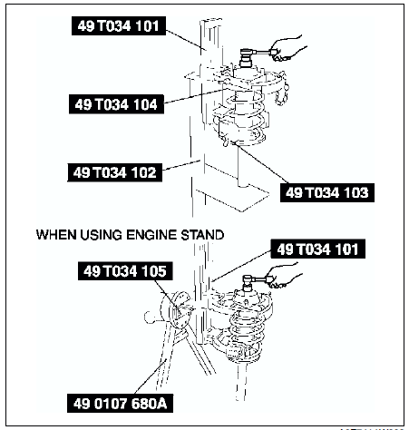
Coil Spring Installation Note
1. Temporarily install the coil spring, dust boot and mounting rubber on the shock absorber so that the lower end of the coil spring is seated on the step of the lower spring seat.
2. Mark the coil spring, dust boot and mounting rubber for proper installation as shown in the figure.
3. Align the marks of the coil spring and dust boot. Protect the coil spring and dust boot using a piece of cloth, then set the SSTs
.
4. Compress the coil spring using the SSTs
.
5. Install the shock absorber so that the lower end of the coil spring is seated on the step of the lower spring seat.
6. Make sure that the marks on the shock absorber and dust boot are aligned.
7. Install the mounting rubber and piston rod nut, then remove the SSTs
.
Piston rod nut tightening torque 39.2-52.9 N·m
{4.00-5.39 kgf·m, 29.0-39.0 ft·lbf}
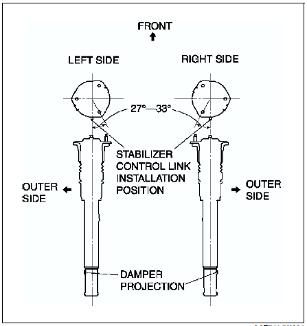
Front Shock Absorber and Coil Spring Installation Note
Install the stud bolts at a 27°-33° angle from where the stabilizer control link is installed (center line), towards the inner side of the vehicle.
Damper Fork Installation Note
1. Align the gap of the damper fork with the projections of the damper.
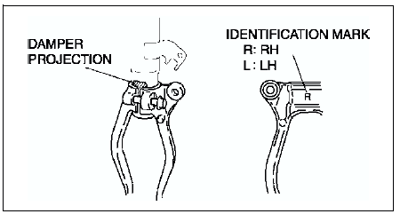
2. Tighten the bolt.
 Front suspension
...
 Front shock absorber inspection
1. Remove the front shock absorber from the vehicle.
2. Inspect for damage and oil leakage.
3. Inspect the rubber bushing for deterioration and wear.
4. Compress and extend the shock piston at leas ...
Other materials:
Mazda 6 Service Manual: Drive shaft (mtx) disassembly/assembly
1. Disassemble in the order indicated in the table.
2. Assemble in the reverse order of disassembly.
Clip Disassembly Note
1. Mark the drive shaft and outer ring for proper assembly.
Caution
Mark with paint; do not use a punch.
2. Remove the clip.
Balls, Inner Ring, Cage Disassembl ...
Mazda 6 Service Manual: Front crossmember removal/installation
1. Remove the under cover.
2. Remove the splash shield.
3. Remove the front auto leveling sensor. (See FRONT AUTO LEVELING SENSOR
REMOVAL/INSTALLATION.)
4. Remove the transverse member. (See TRANSVERSE MEMBER
REMOVAL/INSTALLATION.)
5. Remove the steering gear and linkage, and pipe assembly i ...