Mazda 6 Service Manual: Fuel injector removal/installation
Caution
- Disconnecting/connecting the quick release connector without cleaning it may possibly cause damage to the fuel pipe and quick release connector. Always clean the quick release connector joint area before disconnecting/connecting using a cloth or soft brush, and make sure that it is free of foreign material.
1. Complete the BEFORE REPAIR PROCEDURE. (See BEFORE REPAIR PROCEDURE.)
2. Disconnect the negative battery cable.
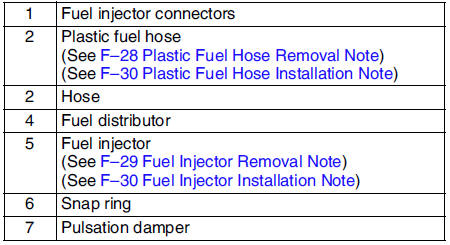
3. Remove in the order indicated in the table.
4. Install in the reverse order of removal.
5. Complete the AFTER REPAIR PROCEDURE. (See AFTER REPAIR PROCEDURE.)
Plastic Fuel Hose Removal Note
Caution
- The quick release connector may be damaged if the tab is bent excessively. Do not expand the tab over the stopper.
1. Disconnect the quick release connector.
(1) Push the tab on the locking coupler 90 degrees
until it stops.
(2) Pull the fuel hose straight back.
Note
- The stopper may be removed from the quick connector. Take care not
to lose it.
Reinstall it to the quick release connector before reconnecting the fuel line.
- The locking coupler has two internal locking tabs which retain the fuel pipe. Be sure that the tab on the locking coupler is rotated until it stops to release two internal locking tabs.
2. Cover the disconnected quick release connector and fuel pipe with vinyl sheets or the like to prevent them from being scratched or contaminated with foreign material.
Fuel Injector Removal Note
Caution
- Use of a deformed injector retaining clip will cause the injector to not engage correctly. Always use a new clip when reattaching the injector, otherwise it may cause the injector to rotate.
1. Insert a screwdriver between the injector cup and the clip fingers.
Note
- When rotating the screwdriver to spread the clip fingers, deform them sufficiently to make sure they release from the notched edge of the injector cup.
2. Rotate the screwdriver to spread the clip fingers and remove them from the injector cup.
3. Pull the injector and clip out of the rail.
4. Remove the clip from the injector according to the following:
(1) Grasp the clip with a pair of pliers.
(2) Pull the clip parallel to the injector groove, and remove it from the injector.
(3) Discard the clip.
Fuel Injector Installation Note
1. Lightly lubricate the injector groove and O-ring.
2. Pre-attach a new clip in the injector groove.
Note
- When the clip is attached correctly, the central area of the injector and the clip finger positions are aligned.
3. Hold the injector firmly, push the clip into the injector until the clip stops sliding.
4. Verify that the injector connector position is correct, and press the injector and clip into the injector cup. Continue pressing until the clip contacts the lower surface of the injector cup.
5. Verify that the injector and clip are correctly attached with the clip locked onto the injector cup notch.
Plastic Fuel Hose Installation Note
Note
- A checker tab is integrated with quick release connector for new plastic fuel hoses. The checker tab will be released from the quick release connector after it is completely engaged with the fuel pipe.
1. When the retainer is not removed, perform the following procedure.
(1) Inspect the fuel pump unit sealing surface for damage and deformation, and replace as necessary.
- If the quick release connector O-ring is damaged, replace the plastic fuel hose.
(2) Slightly apply clean engine oil to the sealing surface of the fuel pump unit.
(3) Align the fuel pipe on the fuel pump unit and quick release connector so that the tabs of the retainer are correctly fitted into the quick release connector. Push the quick release connector straight into the retainer until a click is heard.
(4) Lightly pull and push the quick release connector a few times by hand and verify that it can move 2.0-3.0 mm {0.08-0.11 in}
and it is connected securely.
- If quick release connector does not move at all, verify that O-ring is not damaged and slipped, and reconnect the quick release connector.
2. When the retainer is removed, perform the following procedure.
 Fuel pump unit inspection
Caution
It is normal to hear the fuel pump operating when the ignition
switch is turned to the ON position.
Note
To improve startability, the fuel pump control operates the fuel
pump ...
 Fuel injector inspection
Operation Test
Carry out the Fuel Injector Operation Inspection. (See Fuel Injector
Operation Inspection.)
If not as specified, perform the further inspection for the fuel
injectors.
Resi ...
Other materials:
Mazda 6 Service Manual: Barometric pressure (baro) sensor inspection
Note
Perform the following inspection only when directed.
The following vacuum values are indicated by relative pressure
from the barometric pressure sensor.
1. Connect the SSTs (WDS or equivalent) to the DLC-2.
2. Turn the ignition switch to ON.
3. Select BARO on the SSTs (WDS or equi ...
Mazda 6 Service Manual: High-mount brake light removal/installation
4SD
In-vehicle-type
1. Disconnect the negative battery cable.
2. Remove in the order indicated in the table.
3. Install in the reverse order of removal.
Rear spoiler type
1. Disconnect the negative battery cable.
2. Remove the rear spoiler. (See REAR SPOILER REMOVAL/INSTALLATION)
3. Remo ...