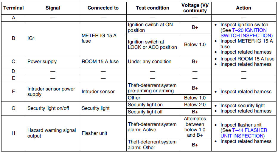
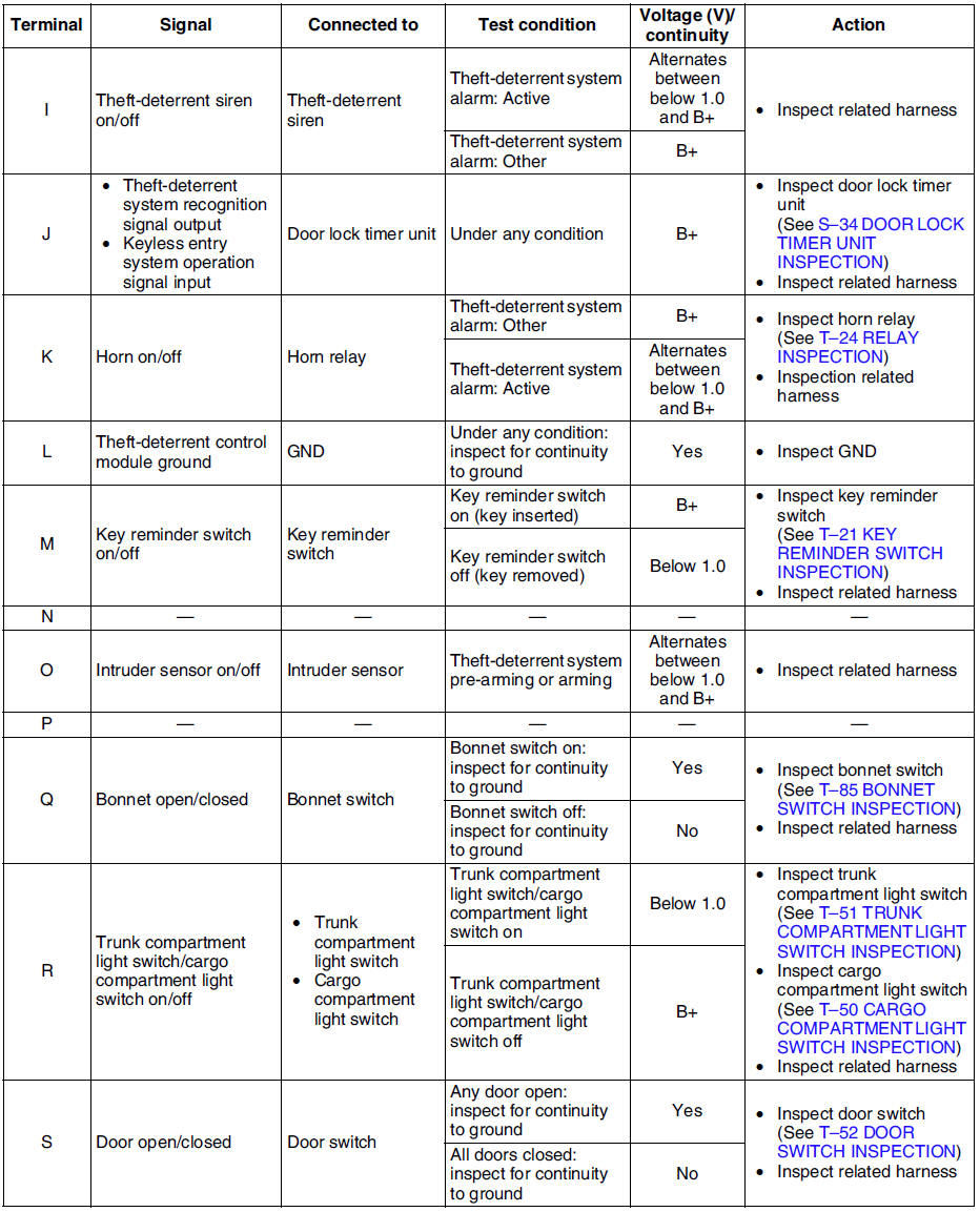
Mazda 6 Service Manual: Theft-deterrent control module inspection
1. Remove the theft-deterrent control module without disconnecting the connectors.
2. Measure the voltage at the theft-deterrent control module terminals as indicated below.
3. Disconnect the theft-deterrent control module connector before inspecting for continuity at terminals L, Q, S, T, and V.
4. If not as specified, inspect the parts listed under Action.
- If the parts and wiring harnesses are okay but the system still does not work properly, replace the theft-deterrent control module.
Terminal Voltage Table (Reference)

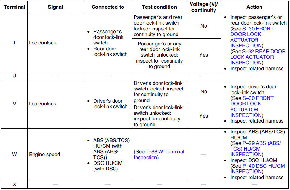
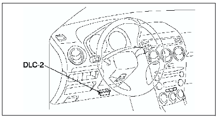
W Terminal Inspection
1. Connect SST
(WDS or equivalent) to the vehicle DLC-2 16-pin connector.
2. Access and monitor RPM of PID using SST (WDS or equivalent).
- If engine speed signal normal, go to next step.
- If engine speed signal abnormal, inspect the ABS (ABS/TCS) HU/CM, DSC HU/CM and related wiring harness.
3. Inspect for continuity between the ABS (ABS/TCS) HU/CM terminal X and the theft-deterrent control module terminal W, or DSC HU/CM terminal AB and the theft-deterrent control module terminal W using an ohmmeter.
- If not continuity, replace the related wiring harness.
- If wiring harness is normal, replace the theft-deterrent control.
 Theft-deterrent control module removal/installation
1. Disconnect the negative battery cable.
2. Remove the center panel module. (See CENTER PANEL MODULE
REMOVAL/INSTALLATION.)
3. Remove in the order indicated in the table.
4. Install in the r ...
 Intruder sensor removal/installation
1. Disconnect the negative battery cable.
2. Remove the headliner.
3. Remove in the order indicated in the table.
4. Install in the reverse order of removal.
...
Other materials:
Mazda 6 Service Manual: Spare Tire
Your Mazda has a temporary spare tire. The temporary spare tire is lighter and
smaller than a conventional tire, and is designed only for emergency use and should
be used only for VERY short periods. Temporary spare tires should NEVER be used
for long drives or extended periods.
WARNING
Do n ...
Mazda 6 Service Manual: Headlight cleaner nozzle removal/installation
1. Remove the front bumper. (See FRONT BUMPER REMOVAL/INSTALLATION)
2. Disconnect the headlight cleaner hose. (See HEADLIGHT CLEANER HOSE
REMOVAL/INSTALLATION)
3. Remove in the order indicated in the table.
4. Install in the reverse order of removal.
5. Adjust the headlight cleaner nozzle. ...