
Mazda 6 Service Manual: Instrument cluster input/output check mode
Note
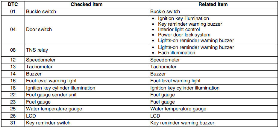
- In this mode, it is possible to check the items in the following chart.
Diagnostic Trouble Code Chart
Note
- Diagnostic trouble codes which are not listed may be indicated, but they cannot be inspected.
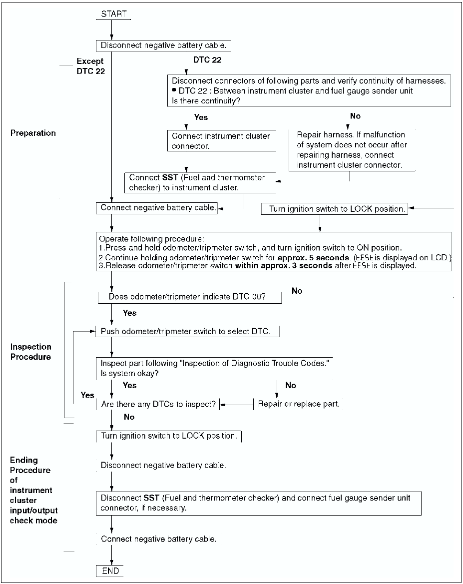
- The diagnostic trouble codes are displayed in numerical order. (While performing the inspection, if you want to inspect a diagnostic trouble code of which the number is smaller than the code number you are currently inspecting, terminate the check mode then repeat the inspection from the beginning.)
- If the speed signal is put into the instrument cluster (the front wheels are rotated) while a code other than DTC 00 is display, the input/output check mode will be cancelled.
- The diagnostic trouble codes can be fast-forwarded by pushing and holding the odometer/tripmeter switch for 1 second or more.
Operating Order
Checking Order
Note
- When inspecting more than two DTCs, perform the inspection by following the priority order of inspection indicated in the chart below.

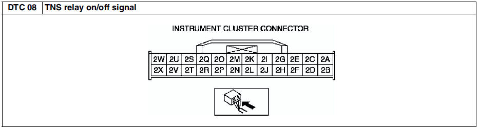
Inspection of Diagnostic Trouble Codes
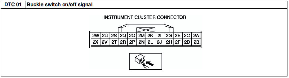
Diagnostic procedure
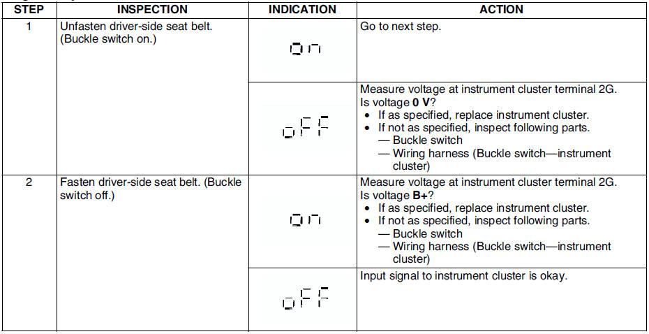
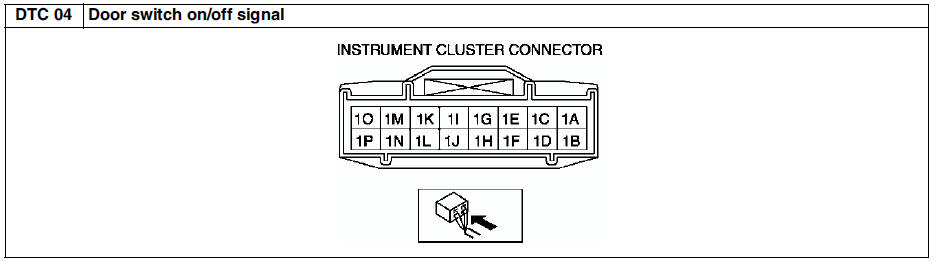
Diagnostic procedure
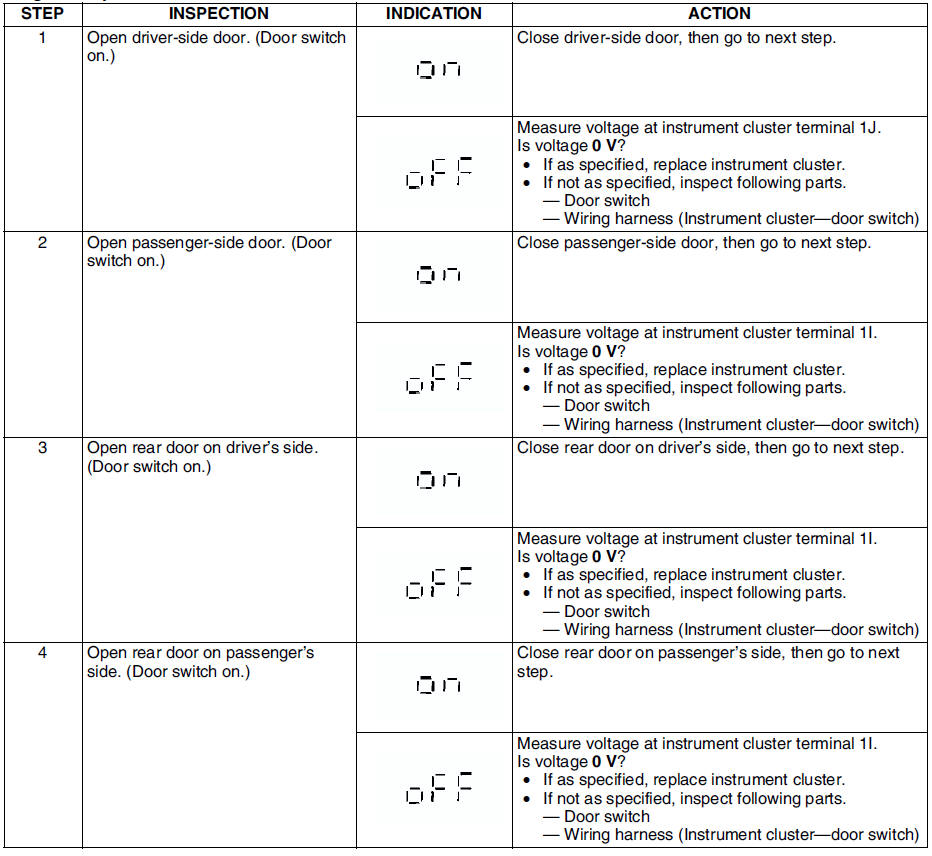
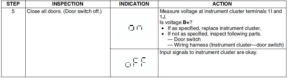
Diagnostic procedure
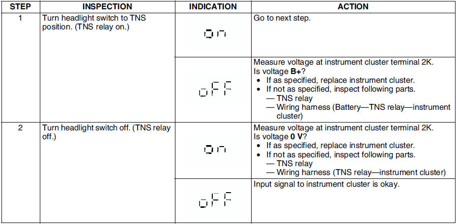
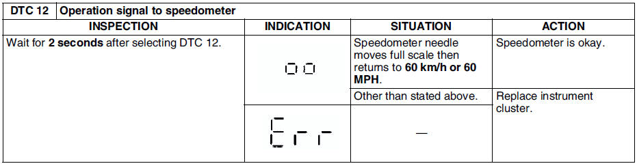
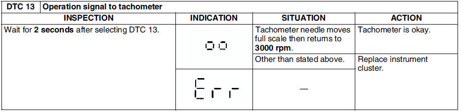


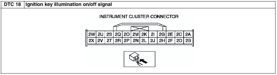
Diagnostic procedure
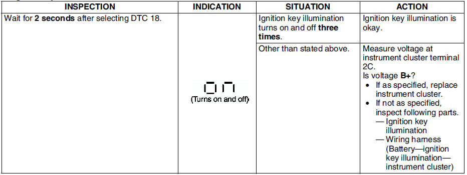
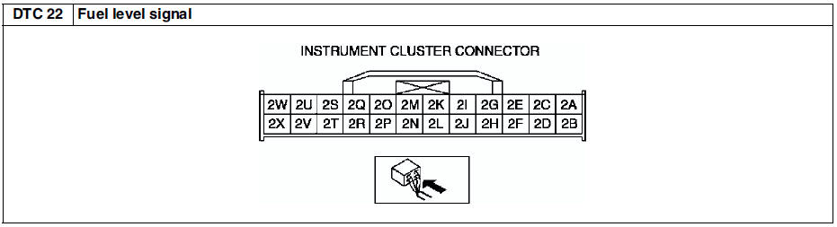
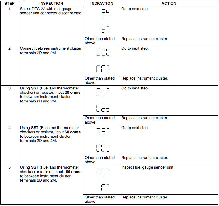
Diagnostic procedure
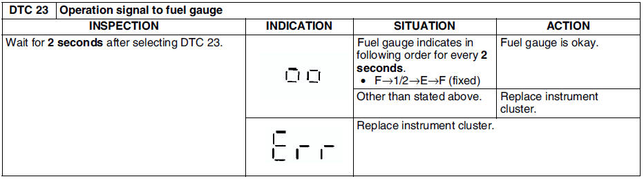
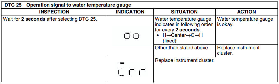

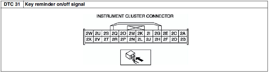
Diagnostic procedure
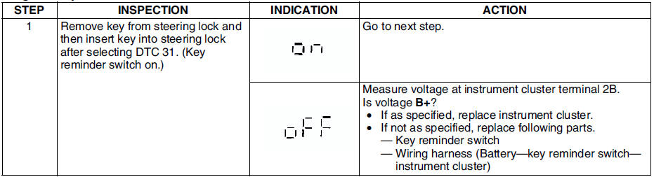
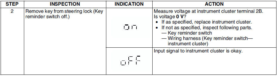
 Instrument cluster repair
Note
The needle of speedometer or tachometer may continue to rotate
clockwise until it indicates over maximum graduation. If a customer
complains of this concern, repair the needle position ...
 Pid/data monitor and record procedure
1. Connect SST (WDS or equivalent) to the vehicle DLC-2 16-pin
connector.
2. Access and monitor PIDs using SST (WDS or equivalent).
Monitor Item Table
The PID/DATA monitoring items for the i ...
Other materials:
Mazda 6 Service Manual: Anti-theft system
Alarm Conditions
If the anti-theft system protection has been activated, any one of the
following conditions will trigger the system:
- Disconnected battery cable
- Discharged battery
- Disconnected audio unit connectors
If the system is triggered, the audio unit will then be ...
Mazda 6 Service Manual: Steering wheel and column inspection
Steering Wheel Play Inspection
With the wheels in the straight-ahead position, gently turn the steering
wheel to the left and right and verify that the play is within the
specification.
If the play exceeds the specification, either the steering joints are
worn or the backlash of the stee ...