
Mazda 6 Service Manual: Joint shaft removal/installation
Caution
- Performing the following procedures without first removing the ABS wheel-speed sensor may possibly cause an open circuit in the harness if it is pulled by mistake. Before performing the following procedures, remove the ABS wheel-speed sensor and fix it to an appropriate place where the sensor will not be pulled by mistake while the vehicle is being serviced.
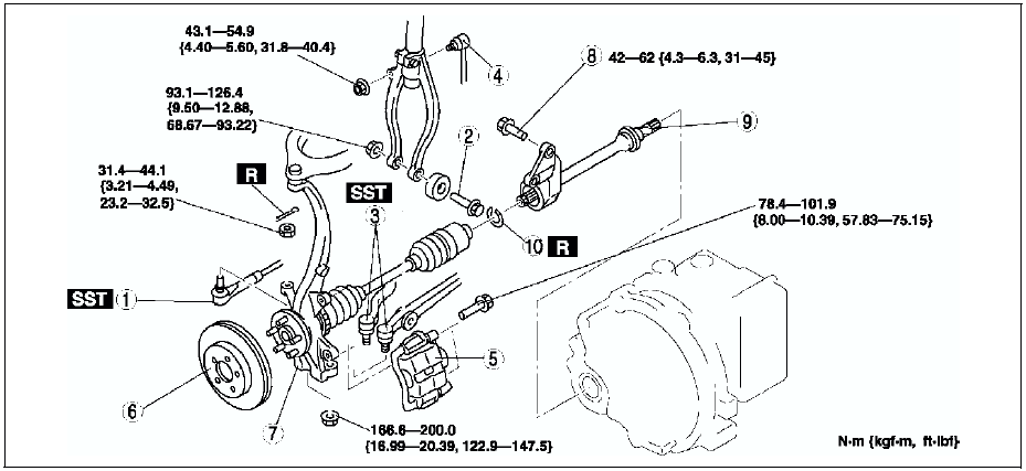
1. Drain the transaxle oil. (See AUTOMATIC TRANSAXLE FLUID (ATF) REPLACEMENT.) (See TRANSAXLE OIL REPLACEMENT.)
2. Remove the ABS sensor. (See FRONT ABS WHEEL-SPEED SENSOR REMOVAL/INSTALLATION.)
3. Remove in the order indicated in the table.
4. Install in the reverse order of removal.
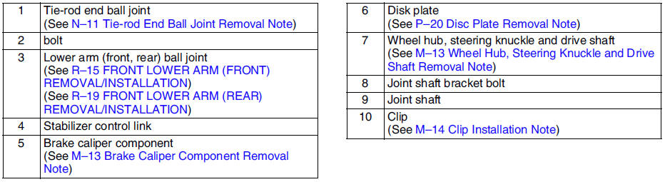
Brake Caliper Component Removal Note
Suspend the caliper aside with wire.
Wheel Hub, Steering Knuckle and Drive Shaft Removal Note
Caution
- The sharp edges of the joint shaft can slice or puncture the oil seal. Be careful when removing the joint shaft from the transaxle.
1. Pull the joint shaft straight out.
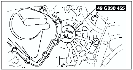
2. Install the SST
into the transaxle to hold the side gears after the joint shaft is removed.
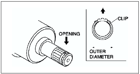
Clip Installation Note
1. Install a new clip onto the joint shaft with the opening facing upward. Ensure that the diameter of the clip does not exceed the specification on installation.
2. After installation, measure the outer diameter. If it exceeds the specification, repeat Step 1 using a new clip.
Outer diameter specification 31.2 mm {1.23 in} max.
 Joint shaft pre-inspection
1. Verify that the joint shaft is not twisted or cracked.
Replace it as necessary.
2. Turn the joint shaft by hand and verify that the bearing rotates smoothly
and freely.
Replace it as n ...
 Joint shaft disassembly/assembly
1. Disassemble in the order indicated in the table.
2. Assemble in the reverse order of disassembly.
Joint Shaft Disassembly Note
Disassemble the joint shaft.
Bearing Disassembly Note
Remov ...
Other materials:
Mazda 6 Service Manual: Starting the Engine
WARNING
Radio waves from the key may affect medical devices such as pacemakers:
Before using the key near people who use medical devices, ask the medical device
manufacturer or your physician if radio waves from the key will affect the device.
NOTE
The key must be carried because the key c ...
Mazda 6 Service Manual: Procedures for determining the location of a malfunction
System Wiring Diadram
PCM
1. Check the display of DTC U0121 and/or U0155, using the SST (WDS or
equivalent). (See DTC TABLE.)
2. Referring to the following table, determine the malfunctioning part of the
CAN system.
ABS/TCS HU/CM or DSC HU/CM
1. Accec and monitor the PCM MSG and IC MSGo ...