Mazda 6 Service Manual: Oil cooler disassembly/assembly
1. Disassemble in the order indicated in the table.
2. Assemble in the reverse order of disassembly.
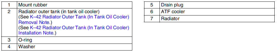
Radiator Outer Tank (In Tank Oil Cooler) Removal Note
1. Inspect the height of the header tabs.
2. Insert the end of a medium tip screwdriver between the end of the header tab and the outer tank.
Note
- Do not open more tabs than necessary for tank removal.
3. Pivot the screwdriver to pry the tab away from the tank and repeat the procedure for each tab.
4. Remove the radiator outer tank and O-ring (gasket) from the core header when all of the tabs are opened.
Note
- If any header tabs are missing from the core, replace the radiator.
5. Inspect the gasket surface of the radiator core header to ensure it is clean and free of foreign material or damage.
6. Inspect the radiator outer tank for warping. If it is warped, replace radiator tank.
Radiator Outer Tank (In Tank Oil Cooler) Installation Note
1. Install a new O-ring and ensure it is not twisted.
Note
- The old O-ring must be replaced.
2. Position the radiator tank in the original direction to the core using care not to scratch the tank sealing surface with the header tabs.
Note
- Step 3 will set jaw opening to the correct specification.
3. With the jaws of locking-type pliers (vise grips) closed and locked, turn the adjusting screw to position the jaws against the drill bit with the diameter measured (height) in removal procedure
Tighten the lock nut on the adjusting screw against the handle to lock the adjustment in place.
4. Squeeze the header tabs down in order as shown against the lip of radiator outer tank base with locking-type pliers while rotating the pliers toward the tank.
5. Verify the height of the header tabs is same as the height before removal.
6. Inspect for leakage from radiator. (See ENGINE COOLANT LEAKAGE INSPECTION.)
 Oil cooler removal/installation
1. Disconnect the negative battery cable.
2. Drain the ATF into a container. (See AUTOMATIC TRANSAXLE FLUID (ATF)
REPLACEMENT.)
3. Remove the radiator. (See RADIATOR REMOVAL/INSTALLATION.)
4. Rem ...
 Drive plate removal/installation
1. Remove the transaxle.(See AUTOMATIC TRANSAXLE REMOVAL/INSTALLATION.)
2. Remove in the order indicated in the figure.
3. Install in the reverse order of removal.
Drive Plate Mounting Bolts Re ...
Other materials:
Mazda 6 Service Manual: Seat Belt Extender
If your seat belt is not long enough, even when fully extended, a seat belt extender
may be available to you at no charge from your Authorized Mazda Dealer.
This extender will be only for you and for the particular vehicle and seat. Even
if it plugs into other seat belts, it may not hold in the ...
Mazda 6 Service Manual: Intermittent concern troubleshooting
Vibration Method
1. If malfunction occurs or becomes worse while driving on a rough road or
when engine is vibrating, perform the steps below.
Note
There are several reasons vehicle or engine vibration could cause
an electrical malfunction. Some of the things to check for are:
...