Mazda 6 Service Manual: Procedures for determining the location of a malfunction
System Wiring Diadram
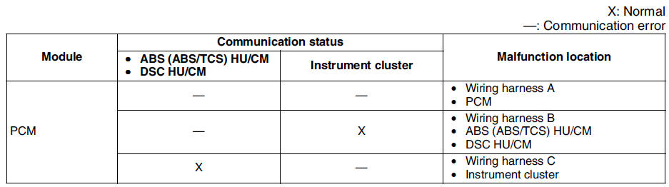
PCM
1. Check the display of DTC U0121 and/or U0155, using the SST
(WDS or equivalent). (See DTC TABLE.)
2. Referring to the following table, determine the malfunctioning part of the CAN system.
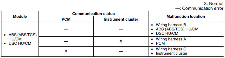
ABS/TCS HU/CM or DSC HU/CM
1. Accec and monitor the PCM MSG and IC MSGof PID using the SST
(WDS or equivalent).
2. Referring to the PID/DATA MONITOR, confirm the display status of the PID. (See PID/DATA MONITOR TABLE.)
3. Referring to the following table, determine the malfunctioning part of the CAN system.
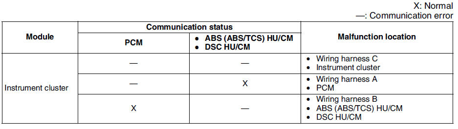
Instrument Cluster
1. Accec and monitor the PCM MSG and ABS MSG of PID using the SST
(WDS or equivalent).
2. Referring to the PID/DATA MONITOR, confirm the display status of the PID. (See PID/DATA MONITOR TABLE.)
3. Referring to the following table, determine the malfunctioning part of the CAN system.

 Dtc u0073, u1900, u2516
Diagnostic procedure
...
Other materials:
Mazda 6 Service Manual: Foreword
Outline
There are two on-board diagnostic functions: Operation mode, which
inspects for and indicates correct operation of the input signals to the
control module, and condition detection mode, which indicates troubles in
the system.
The two functions can be done using either of the f ...
Mazda 6 Service Manual: Variable tumble control system (vtcs) shutter valve actuator inspection
1. Remove the air hose. (See INTAKE-AIR SYSTEM REMOVAL/INSTALLATION.)
2. Disconnect the vacuum hose from the VTCS shutter valve actuator.
3. Connect a vacuum pump to the VTCS shutter valve actuator.
4. Apply vacuum and verify that the rod moves.
If the rod dose not move, replace the intake ...