Mazda 6 Service Manual: Selector lever removal/installation
1. Disconnect the negative battery cable.
2. Remove battery and battery tray.
3. Remove the air cleaner compornent. (See INTAKE-AIR SYSTEM REMOVAL/INSTALLATION.)
4. Remove the console.
5. Remove the dashboard compleat. (See DASHBOARD REMOVAL/INSTALLATION.)
6. Remove the SAS control module. (See SAS UNIT REMOVAL/INSTALLATION.)
7. Remove the climate control unit. (See CLIMATE CONTROL UNIT REMOVAL.) (See CLIMATE CONTROL UNIT INSTALLATION.)
8. Remove the rear heat duct. (See REAR HEAT DUCT REMOVAL/INSTALLATION.)
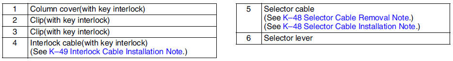
9. Remove in the order shown in the figure.
10. Remove the battery, battery tray and battery bracket.
11. Install in the reverse order of removal.
Selector Cable Removal Note
1. Remove the clip.
2. Remove the selector cable.
Selector Cable Installation Note
1. Install the selector cable to the selector lever certainly.
2. Install the selector cable to the bracket certainly.
Note
- Step 3, 4 is for the selector cable replacement only.
3. Verify that the selector lever is in P position.
4. Lock the lock piece of the selector cable (selector lever side) in the order shown in the figure.
5. Verify that the manual shaft is in P position.
Caution
- Bending the selector cable in the manner shown in the figure will damage the cable and it may become loose when shifted. When installing the selector cable, hold it straight.
Note
- Install the selector lever to the manual shaft lever with the spring side of the selector cable end facing the front of the vehicle.
6. Install the selector lever to the manual shaft lever in such a way that the selector cable does not bear a load.
7. Confirm that the end of the manual shift lever sticks out of the end of the selector cable.
8. Install the selector cable to the selector cable securely bracket.
Interlock Cable Installation Note
1. Verify that the shift the selector lever in P position and ignition key is in LOCK position.
2. Press the lock unit onto the brake pedal stopper bracket.
3. From this position, slide the lock unit to fix the lock unit hook into the bracket hole securely as shown in the figure.
Caution
- Allowing the interlock cable to be bent or twisted during installation can affect the lock unit operation.
4. Install the interlock cable end onto the cam pin on the selector lever.
5. Fit the interlock cable in the Ugroove in the selector lever base plate, and install the clip.
Caution
Applying a load to the interlock cable while pressing the lock piece in can affect the lock unit operation.
e
6. Press the interlock cable lock piece in unitl it is locked.
Note
- Step 7 is for the interlock cable replacement only.
7. Remove the lock unit pin as shown in the figure.
8. Turn the ignition key in ACC position.
9. Install the interlock cable to the key cylinder.
10. Slide the outer casing to the key cylinder, and insert the clip over the convex part of the outer casing.
 Selector cable adjustment
1. Remove the center console.
2. Shift the selector lever to P position.
3. Unlock the lock piece of the selector cable (selector lever side) in the
order shown in the figure.
4. Verify that th ...
 Selector lever disassembly/assembly
1. Disassemble in the order shown in the figure.
2. Assemble in the reverse order of disassembly.
Connector Disassembly Note
1. Insert a thin piece of metal from the terminal side of the connec ...
Other materials:
Mazda 6 Service Manual: Fuel pump unit disassembly/assembly
Warning
Fuel line spills and leakage are dangerous. Fuel can ignite and
cause serious injuries or death and damage. Fuel can also irritate skin and
eyes. To prevent this, do not damage the sealing surface of the fuel pump
unit when removing or installing.
1. Disassemble in the order ...
Mazda 6 Service Manual: Transaxle fluid temperature (tft) sensor removal/installation
Warning
When the transaxle and ATF are hot, they can badly burn. Turn off
the engine and wait until they are cool before replacing the ATF.
1. Remove the oil pan. (See CONTROL VALVE BODY REMOVAL.)
2. Disconnect the TFT sensor connector.
3. Remove the TFT sensor.
4. Install a TFT senso ...