Mazda 6 Service Manual: Throttle position (tp) sensor inspection
Note
- Perform the following inspection only when directed.
Resistance Inspection
1. Perform the following test only when directed.
- If as specified but TP PID value is out of specification, inspect resistance of TP sensor.
- If not as specified, inspect the following:
- Accelerator cable free play (See ACCELERATOR CABLE INSPECTION/ADJUSTMENT.)
2. Disconnect the TP sensor connector.
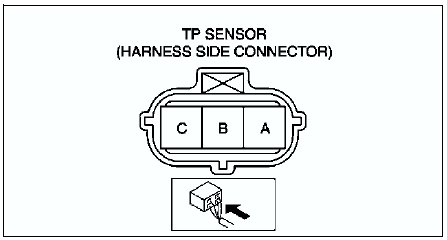
3. Verify that the resistance between TP sensor terminals A and B changes smoothly while opened and closed the throttle valve slowly.
- If not verified, replace TP sensor.
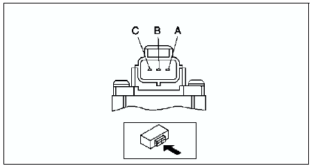
4. Measure the resistance between TP sensor terminals A and C using an ohmmeter.
- If not as specified, replace the TP sensor.
- If as specified, but TP PID value is out of specification, perform the Circuit Open/Short Inspection.
Specification
3.2-4.8 kilohms
Circuit Open/Short Inspection
1. Disconnect the PCM connector. (See PCM REMOVAL/INSTALLATION.)
2. Inspect the following wiring harnesses for open or short. (Continuity check)
Open circuit
- If there is no continuity, the circuit is open. Repair or replace the harness.
- TP sensor terminal A (harness-side) and PCM terminal 2H (harness-side)
- TP sensor terminal B (harness-side) and PCM terminal 2A (harness-side)
- TP sensor terminal C (harness-side) and PCM terminal 2K (harness-side)
Short circuit
- If there is continuity, the circuit is shorted. Repair or replace the harness.
- TP sensor terminal C (harness-side) and power supply
- TP sensor terminal C (harness-side) and body GND
- TP sensor terminal B (harness-side) and power supply
- TP sensor terminal B (harness-side) and body GND
- TP sensor terminal A (harness-side) and power supply
 Mass air flow (maf) sensor inspection
Voltage Inspection
Note
Perform the following inspection only when directed.
1. Visually inspect for the following on the MAF sensor.
Damage
Cracks
Terminal bends
Terminal rust
...
 Manifold absolute pressure (map) sensor inspection
Note
Perform the following inspection only when directed.
The following vacuum values are indicated by relative pressure
from the MAP sensor.
1. Connect the SSTs (WDS or equivalent) to the ...
Other materials:
Mazda 6 Service Manual: Passenger-side air bag module removal/installation
Warning
Handling the air bag module improperly can accidentally deploy the
air bag module, which may seriously injure you. Read AIR BAG SYSTEM SERVICE
WARNINGS before handling the air bag module. (See SERVICE WARNINGS.)
Due to the adoption of 2-step deployment control in both the
pass ...
Mazda 6 Service Manual: Intake-air system removal/installation
Warning
When the engine and intake-air system are hot, they can badly
burn. Turn off the engine and wait until they are cool before removing the
intake-air system.
Fuel vapor is hazardous. It can easily ignite, causing serious
injury and damage. Always keep sparks and flames away from ...