Mazda 6 Service Manual: Valve clearance adjustment
1. Disconnect the negative battery cable.
2. Remove the tire (RH).
3. Remove the splash shield (RH).
4. Remove the spark plugs. (See SPARK PLUG REMOVAL/INSTALLATION.)
5. Remove the high-tension lead.
6. Remove the oil control valve (OCV) connector.
7. Remove the ventilation hose.
8. Remove the cylinder head cover.
9. Remove the drive belt. (See DRIVE BELT REPLACEMENT.)
10. Remove the joint shaft from the front drive shaft (RH). (See DRIVE SHAFT REMOVAL/INSTALLATION.)
11.Remove the engine front cover lower blind plug.
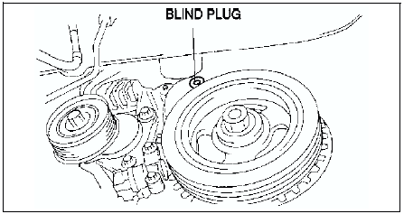
12. Remove the engine front cover upper blind plug.
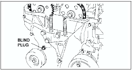
13. Remove the cylinder block lower blind plug.
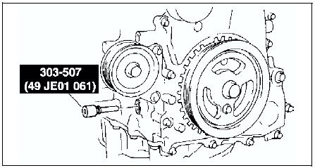
14. Install the SST
as shown.
15. Turn the crankshaft clockwise the crankshaft is in No.1 cylinder TDC position.
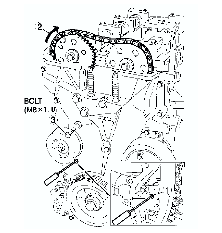
16. Loosen the timing chain.
(1) Using a suitable screwdriver or equivalent tool, unlock the chain tensioner ratchet.
(2) Turn the exhaust camshaft clockwise using a suitable wrench on the cast hexagon and loosen the timing chain.
(3) Placing the suitable bolt (M6 X 1.0 length 25mm-35mm {0.99in-1.37in})
at the engine front cover upper blind plug, secure the chain guide at the position where the tension is released.
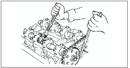
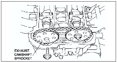
17. Hold the exhaust camshaft using a suitable wrench on the cast hexagon as shown.
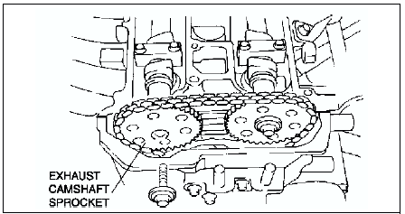
18. Remove the exhaust camshaft sprocket.
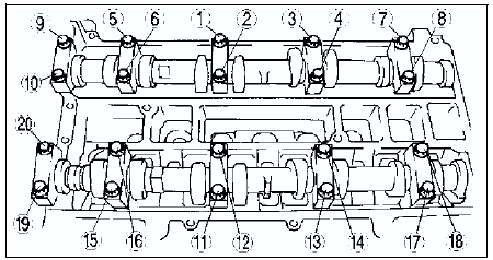
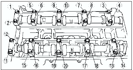
19. Loosen the camshaft cap bolts in several passes in the order shown.
Note
- The cylinder head and the camshaft caps are numbered to make sure they are reassembled in their original position. When removed, keep the caps with the cylinder head they were removed from. Do not mix the caps.
20. Remove the camshaft.
21. Remove the tappet.
22. Select proper adjustment shim.
New adjustment shim = Removed shim thickness + Measured valve clearance - Standard valve clearance (IN: 0.25 mm
{0.0098 in}, EX: 0.30 mm {0.0118 in})Standard [Engine cold] IN: 0.220.28 mm {0.0087-0.0110 in} (0.25±0.03 mm {0.0098±0.0011 in})
EX: 0.27-0.33 mm {0.01060.0130 in} (0.30±0.03 mm {0.0118±0.0011 in})
23. Install the camshaft with No.1 cylinder aligned with the TDC position.
24. Tighten the camshaft cap bolt using the following two steps.
(1) Tighten to 5.0-9.0 N·m {51.0-91.7 kgf·cm, 44.3-79.5 in·lbf}.
(2) Tighten to 14.0-17.0 N·m {1.5-1.7 kgf·m, 10.4-12.5 ft·lbf}
.
25. Install the exhaust camshaft sprocket.
Note
- Do not tighten the bolt for the camshaft sprocket during this step. First confirm the valve timing, then tighten the bolt.
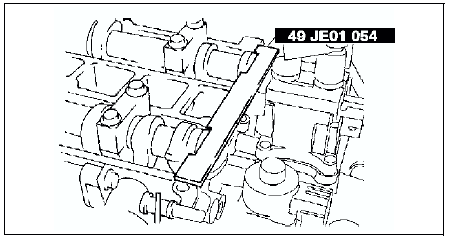
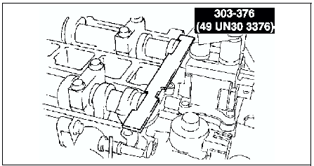
26. Install the SST
to the camshaft as shown.
European countries
Except European countries
27. Remove the M6 x 1.0 bolt (length 25mm-35mm {0.99in-1.37in})
from the engine front cover to apply tension to the timing chain.
28. Turn the crankshaft clockwise the crankshaft is in the No.1 cylinder TDC position.
29. Hold the exhaust camshaft using a suitable wrench on the cast hexagon as shown.
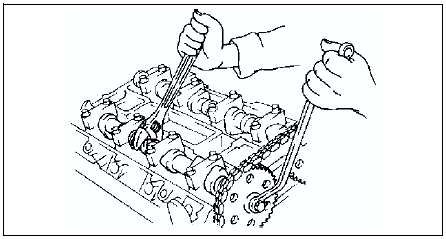
30. Tighten the exhaust camshaft sprocket lock bolt.
Tightening torque: 69-75 N·m {7.10-7.6 kgf·m, 50.9-55.3 ft·lbf}
31. Remove the SST
from the camshaft.
32. Remove the SST
from the block lower blind plug.
33. Rotate the crankshaft clockwise two turns until the TDC position.
- If not aligned, loosen the crankshaft pulley lock bolt and repeat from Step 14.
34. Apply silicone sealant to the engine front cover upper blind plug.
35. Install the engine front cover upper blind plug.
Tightening torque: 10 N·m {1.0 kgf·m, 7.4 ft·lbf}
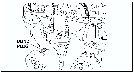
36. Install the cylinder block lower blind plug.
Tightening torque:
18-22 N·m {1.9-2.2 kgf·m, 13.3-16.2 ft·lbf}
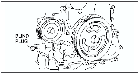
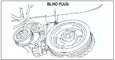
37. Install the new engine front cover lower blind plug.
Tightening torque: 12 N·m {1.2 kgf·m, 8.9 ft·lbf}
38. Connect the front drive shaft (RH) and the joint shaft. (See DRIVE SHAFT REMOVAL/INSTALLATION)
39. Install the drive belt. (See DRIVE BELT REPLACEMENT.)
40. Install the cylinder head cover. (See Cylinder Head Cover Installation Note.)
41. Install the ventilation hose.
42. Install the oil control valve (OCV) connector.
43. Install the high-tension lead. (See HIGH-TENSION LEAD REMOVAL/INSTALLATION.)
44. Install the spark plugs. (See SPARK PLUG REMOVAL/INSTALLATION.)
45. Install the splash shield (RH).
46. Install the tire (RH).
 Valve clearance inspection
1. Disconnect the negative battery cable.
2. Remove the tire (RH).
3. Remove the splash shield (RH).
4. Remove the spark plugs. (See SPARK PLUG REMOVAL/INSTALLATION.)
5. Remove the high-tension le ...
 Compression pressure
COMPRESSION INSPECTION
Warning
Hot engines and oil can cause severe burns. Be careful not to burn
yourself during removal/installation of each component.
1. Verify that the battery is fully ...
Other materials:
Mazda 6 Service Manual: Manual Shift Mode
The manual shift mode gives you the feel of driving a manual transaxle vehicle
by allowing you to operate the selector lever manually. This allows you to control
engine rpm and torque to the drive wheels much like a manual transaxle when more
control is desired.
To change to manual shift mode ...
Mazda 6 Service Manual: Clutch pedal removal/installation
1. Remove the battery and battery tray. (European (L.H.D.) and GCC specs.)
2. Remove in the order indicated in the table.
3. Install in the reverse order of removal.
4. After installation, adjust the clutch pedal. (See CLUTCH PEDAL
ADJUSTMENT.)
у
Clutch Pedal Installation Note
Afte ...

