
Mazda 6 Service Manual: A/c unit removal/installation
1. Disconnect the negative battery cable.
2. Discharge the refrigerant from the system. (See RECOVERY.) (See CHARGING.)
3. Drain the engine coolant. (See ENGINE COOLANT REPLACEMENT.)
4. Remove the dashboard. (See DASHBOARD REMOVAL/INSTALLATION.)
5. Remove the theft-deterrent control module. (See THEFT-DETERRENT CONTROL MODULE REMOVAL/INSTALLATION.)
Caution
- If moisture or foreign material enters the refrigeration cycle, cooling ability will be lowered and abnormal noise will occur. Always immediately plug open fittings after removing any refrigeration cycle parts to keep moisture or foreign material out of the cycle.
6. Remove in the order indicated in the table. Do not allow compressor oil to spill.
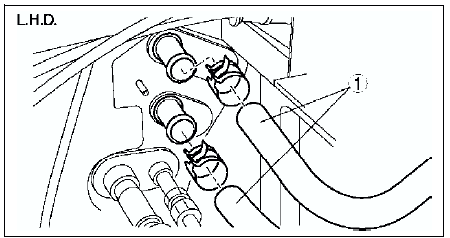
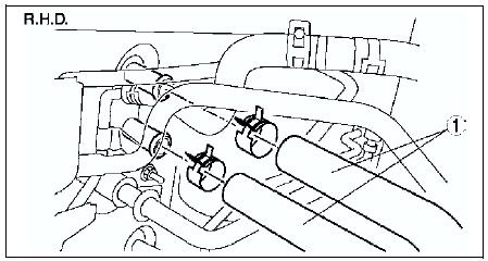
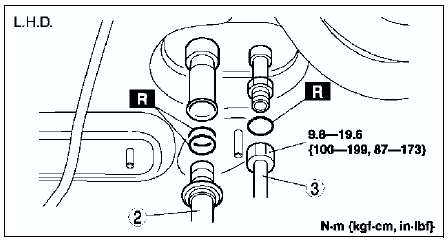
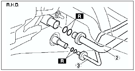
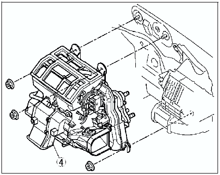
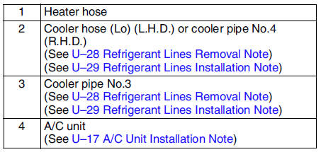
7. Install in the reverse order of removal.
8. Perform the refrigerant system performance test. (See REFRIGERANT SYSTEM PERFORMANCE TEST.)
A/C Unit Installation Note
When installing a new A/C unit or evaporator, add a supplemental amount of ATMOS GU10 compressor oil into the refrigerant cycle.
Supplemental amount (approximate quantity) 25 ml {25 cc, 0.8 fl oz}
 Air filter inspection
1. Remove the air filter.
2. Inspect the air filter.
If the air filter is damaged, excessively dirty, or foul smelling,
replace the air filter.
Note
The air filter cannot be reused by c ...
 A/c unit disassembly/assembly
1. Disassemble in the order indicated in the table.
2. Assemble in the reverse order of disassembly.
Evaporator Temperature Sensor Assembly Note
Assemble the evaporator temperature sensor as ...
Other materials:
Mazda 6 Service Manual: Steering wheel and column inspection
Steering Wheel Play Inspection
With the wheels in the straight-ahead position, gently turn the steering
wheel to the left and right and verify that the play is within the
specification.
If the play exceeds the specification, either the steering joints are
worn or the backlash of the stee ...
Mazda 6 Service Manual: No.8 brake system warning light stays on more than 4 seconds with ignition
switch on
Diagnostic procedure
When performing an asterisked (*) troubleshooting inspection, shake the
wiring harness and connectors while doing the inspection to discover whether
poor contact points are the cause of any intermittent malfunction. If there
is a problem, check to make sure co ...