Mazda 6 Service Manual: Airflow mode actuator inspection
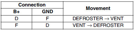
1. Connect battery positive voltage to terminal D or F and ground to terminal F or D of the airflow mode actuator.
2. Verify that the airflow mode actuator operates as shown below.
- If not as specified, replace the airflow mode actuator.
3. Verify that the resistance between the terminals of the airflow mode actuator is as shown in the graph.
- If not as specified, replace the airflow mode actuator.
 Airflow mode actuator removal/installation
1. Disconnect the negative battery cable.
2. Remove the glove compartment.
3. Remove the car navigation unit. (See CAR-NAVIGATION UNIT
REMOVAL/INSTALLATION.)
4. Remove in the order indicated in t ...
 Blower motor removal/installation
1. Disconnect the negative battery cable.
2. Remove in the order indicated in the table.
3. Install in the reverse order of removal. ...
Other materials:
Mazda 6 Service Manual: Actuator cable removal
1. Remove the plug hole plate.
2. Remove the cover from the cruise actuator. (See CRUISE ACTUATOR
REMOVAL/INSTALLATION.)
3. Remove the installation nut and pull the cruise actuator toward you.
4. Move the throttle, and remove the end fitting of the actuator cable from
the throttle.
5. Sque ...
Mazda 6 Service Manual: Windshield wiper arm and blade removal/installation
1. Remove in the order indicated in the table.
2. Install in the reverse order of removal.
3. Adjust the windshield wiper arm and blade. (See WINDSHIELD WIPER ARM AND
BLADE ADJUSTMENT.)
Windshield Wiper Arm Installation Note
Clean the windshield wiper arm connector shafts using a wire brus ...