Mazda 6 Service Manual: Automatic transaxle removal/installation
1. Disconnect the negative battery cable.
2. Remove the battery and battery tray.
3. Remove the aircleaner component. (See INTAKE-AIR SYSTEM REMOVAL/INSTALLATION.)
4. Remove the front tires and splash shield.
5. Remove the under cover.
6. Remove the steering gear and power steering pipe. (See STEERING GEAR AND LINKAGE REMOVAL/INSTALLATION.)
7. Remove the front auto leveling sensor. (See FRONT AUTO LEVELING SENSOR REMOVAL/INSTALLATION.)
8. Drain the ATF. (See AUTOMATIC TRANSAXLE FLUID (ATF) REPLACEMENT.)
Warning
- Improperly jacking a transaxle is dangerous. It can slip off the jack and may cause serious injury.
Caution
- To prevent the torque converter and transaxle from separating, remove the transaxle without tilting it toward the torque converter.
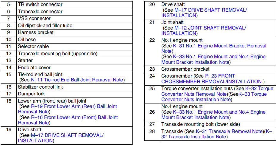
9. Remove in the order shown in the figure.
10. Install in the reverse order of removal.
11. Adjust the headlight zeroset. (See HEADLIGHT ZEROSET.)
12. Add ATF to the specified level. (See AUTOMATIC TRANSAXLE FLUID (ATF) REPLACEMENT.)
13. Carry out the mechanical system test. (See MECHANICAL SYSTEM TEST.)
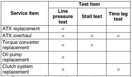
× : Test to be performed after the service work
14. Carry out the road test. (See ROAD TEST.)

No.1 Engine Mount Bracket Removal Note
1. Support the engine using the SST before removing the No.1 engine mount.
2. Remove the No.1 engine mount.
Transaxle Removal Note
1. Loosen the part marked A and lean the engine toward the transaxle.
2. Support the transaxle on a jack.
3. Remove the transaxle mounting bolts.
4. Remove the transaxle.
Transaxle Installation Note
1. Set the transaxle on a jack and lift it.
2. Install the transaxle mounting bolts.
Tightening torque 37.3-52 N·m {3.8-5.3 kgf·m, 28-38 ft·lbf}
Torque Converter Nuts Removal Note
1. Hold the cankshaft pulley to prevent drive plate from rotating.
2. Remove the torque converter nuts from the starter installation hole.
Torque Converter Nuts Installation Note
1. Hold the cankshaft pulley to prevent drive plate from rotating.
Caution
- Loosely and equally tighten the torque converter nuts, then further tighten them to the specified tightening torque.
2. Tighten the torque converter mounting nuts.
Tightening torque 34.3-60.8 N·m {3.5-6.2 kgf·m, 25-45 ft·lbf}
No.1 Engine Mount and No.4 Engine Mount Bracket Installation Note
1. Verify that the engine mount rubbers are installed as shown.
2. By aligning the holes with the stud bolts, install the No.4 engine mount bracket to the transaxle.
3. By aligning the holes with the stud bolts, install the No.1 engine mount to the transaxle.
4. Align the hole of the No.4 engine mount bracket with the No.4 engine mount rubber on vehicle, and temporarily tighten the bolt D.
5. Tighten the nut B,C in order of B→C, then bolt A.
6. Tighten the bolt D.
Tightening torque A, B, C: 66.6-93.1 N·m {6.8-9.4 kgf·m, 50-68 ft·lbf} D: 85.3-116.6 N·m {8.7-11.8 kgf·m, 63-85 ft·lbf}
8. Tighten the bolt D to the No.1 engine mount.
Tightening torque E: 85.3-116.6 N·m {8.7-11.8 kgf·m, 63-85 ft·lbf}
9. Remove the SST
(49 E017 5A0)
 Pcm removal/installation
Remove and install the PCM. (See PCM REMOVAL/INSTALLATION.) ...
 Oil seal replacement
1. Drain the ATF. (See AUTOMATIC TRANSAXLE FLUID (ATF) REPLACEMENT.)
Caution
The oil seal is easily damaged by the sharp edges of the drive
shaft splines. Do not let the splines contact the oi ...
Other materials:
Mazda 6 Service Manual: Seat warmer switch removal/installation
1. Disconnect the negative battery cable.
2. Remove the brake boots panel. (See CONSOLE REMOVAL/INSTALLATION.)
3. Remove in the order indicated in the table.
4. Install in the reverse order of removal.
Seat Warmer Switch Removal Note
Squeeze the tabs of seat warmer switch and pull it forwar ...
Mazda 6 Service Manual: Front/rear abs wheel-speed sensor inspection
Visual Inspection
Remove the wheel and tire, and inspect the sensor for looseness and damage.
Replace the sensor if necessary.
Clearance Inspection
Inspect the clearance between the wheel-speed sensor and the sensor rotor.
Clearance
0.3-1.1 mm {0.012-0.043 in}
Resistance Inspection
...