Mazda 6 Service Manual: Control valve body installation
On-Vehicle Installation
Caution
- Be sure to align the parking rod and the manual valve.
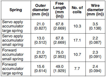
1. Install the accumulator springs and accumulators into the transaxle case.
2. Install the control valve body component.
Tightening torque 7.8-10.8 N·m
{80-110 kgf·cm, 70-95 in·lbf}Bolt length (measured from below the head) B: 40 mm {1.575 in}
No mark: 70 mm {2.756 in}
3. Install the oil strainer.
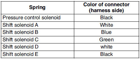
4. Match the harness colors, then connect the solenoid connector and TFT
sensor connector.
5. Install the ground.
Tightening torque 7.8-10.8 N·m {80-110 kgf·cm, 70-95 in·lbf}
6. Apply a light coat of silicon sealant to the contact surfaces of the oil pan and transaxle case.
7. Install the oil pan.
Tightening torque 6-8 N·m {62-81 kgf·cm, 53-70 in·lbf}
8. Install the crossmember. (See FRONT CROSSMEMBER REMOVAL/INSTALLATION.)
9. Install the front tires and splash shield.
10. Install the under cover.
11. Connect the negative battery cable.
12. Add ATF and with the engine idling, inspect the ATF level. (See AUTOMATIC TRANSAXLE FLUID (ATF) REPLACEMENT.)
13. Carry out the mechanical system test. (See MECHANICAL SYSTEM TEST.)
14. Carry out the road test. (See ROAD TEST.)
 Control valve body removal
On-Vehicle Removal
Warning
Using compressed air can cause dirt and other particles to fly
out, causing injury to the eyes. Wear protective eyes whenever using
compressed air.
Caution
...
 Oil cooler flushing
Note
The contaminated cooler line (oil pipes and hoses) and auxiliary
cooler must be flushed completely when ATX is overhauled or replaced.
1. Remove the two oil cooler line hoses and apply ...
Other materials:
Mazda 6 Service Manual: Curtain air bag module removal/installation
Warning
Handling the air bag module improperly can accidentally deploy the air bag
module, which may seriously injure you. Read AIR BAG SYSTEM SERVICE WARNINGS
before handling the air bag module. (See SERVICE WARNINGS.)
1. Turn the ignition switch to LOCK position.
2. Disconnect the nega ...
Mazda 6 Service Manual: Front seat disassembly/assembly
Warning
Handling the front seat (side air bag) improperly can accidentally
deploy the side air bag, which may seriously injure you. Read AIR BAG SYSTEM
SERVICE WARNINGS before handling the front seat. (See SERVICE WARNINGS.)
1. Disconnect the negative battery cable and wait for more tha ...