Mazda 6 Service Manual: Drive shaft (atx) disassembly/assembly
1. Disassemble in the order indicated in the table.
2. Assemble in the reverse order of disassembly.
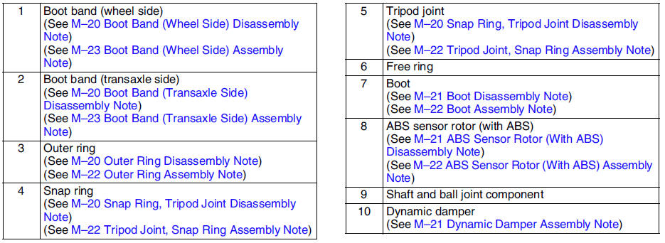
Boot Band (Wheel Side) Disassembly Note
Note
The boot band does not need to be removed unless it is being replaced.
Remove the boot clamp with end clamp pliers as shown and discard the clamp.
Boot Band (Transaxle Side) Disassembly Note
1. Pry up the locking clips using a screwdriver.
2. Pull back the end of the band.
Outer Ring Disassembly Note
1. Mark the outer ring and the shaft for proper assembly.
2. Remove the outer ring.
Snap Ring, Tripod Joint Disassembly Note
1. Mark the shaft and tripod joint for proper assembly.
2. Remove the snap ring using snap-ring pliers.
3. Remove the tripod joint from the shaft.
Caution
- Do not tap the tripod joint with a hammer.
Boot Disassembly Note
Note
- The wheel side boot does not need to be removed unless replacing it or the ball joint and shaft component.
- Do not strip the tape until the boot is assembled.
1. Wrap the shaft splines with tape.
2. Remove the boot.
ABS Sensor Rotor (With ABS) Disassembly Note
Caution
- Do not remove the sensor rotor unless it is necessary.
- Do not reuse the sensor rotor if removed.
Tap the ABS sensor rotor off the drive shaft using a chisel.
Dynamic Damper Assembly Note
1. Install the dynamic damper as shown in the figure.
Standard length
334.7-340.7 mm {13.2-13.4 in}
2. Install the new boot band onto the dynamic damper.
ABS Sensor Rotor (With ABS) Assembly Note
Set a new ABS sensor rotor on the drive shaft and press it on using the SSTs
.
Boot Assembly Note
Note
- The wheel side and transaxle side boots are different.
1. Fill the boot (wheel side) with the specified grease.
Caution
- Do not touch grease with your hand. Apply it from the tube to prevent foreign matter from entering the boot.
Grease amount
90-110 g {3.18-3.88 oz}
2. With the splines of the shaft still wrapped in tape from disassembly, install the boot.
3. Remove the tape.
Tripod Joint, Snap Ring Assembly Note
1. Align the marks and install the tripod joint using a bar and a hammer.
Caution
- Do not damage the roller.
2. Install the new snap ring using snap-ring pliers.
Caution
- Be sure the snap ring engag
Outer Ring Assembly Note
1. Fill the outer ring and boot (transaxle side) with the specified grease.
Caution
- Do not touch grease with your hand. Apply it from the tube to prevent foreign matter from entering the boot.
Grease amount
195-215 g {6.88-7.58 oz}
2. Install the outer ring.
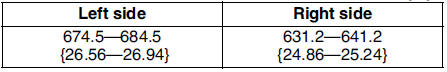
3. Set the drive shaft to the standard length.
Standard length
mm {in}
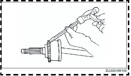
4. Release any trapped air from the boots by carefully lifting up the small end of each boot with a cloth wrapped screwdriver.
Caution
- Do not let grease leak.
- Do not damage the boot.
5. Verify that the drive shaft length is within the standard.
Boot Band (Transaxle Side) Assembly Note
1. Fold the band in the direction opposite to the forward revolving direction of the drive shaft and use pliers to pull it tight.
2. Lock the end of the band by bending the locking clips.
Caution
- Install the band into the groove securely.
Boot Band (Wheel Side) Assembly Note
1. Adjust clearance A by turning the adjusting bolt of the SST
.
Clearance A
2.9 mm {0.11 in}
2. Crimp the wheel side small boot band using the SST
. Verify that clearance B is within the specification.
- If clearance B is more than the specification, reduce clearance A of the
SST
and crimp the boot again.
- If clearance B is less than the specification, replace the boot band,
increase clearance A of the SST
, and crimp the new boot.
Clearance B
2.4-2.8 mm {0.095-0.110 in}
3. Verify that the boot band does not protrude from the boot band installation area.
- If it does, replace the boot band and repeat Steps 2 and 3.
4. Fill the boot with the repair kit grease.
5. Adjust clearance A by turning the adjusting bolt of the SST
.
Clearance A
3.2 mm {0.13 in}
6. Crimp the wheel side big boot band using the SST.
7. Verify that clearance B is within the specification.
- If clearance B is more than the specification, reduce clearance A of the SST and crimp the boot again.
- If clearance B is less than the specification, replace the boot band, increase clearance A of the SST and crimp the new boot.
Clearance B
2.4-2.8 mm {0.095-0.110 in}
8. Verify that the boot band does not protrude from the boot band installation area.
- If it does, replace the boot band and repeat Steps 7 and 8.
 Drive shaft removal/installation
Caution
Performing the following procedures without first removing the ABS
wheel-speed sensor may possibly cause an open circuit in the harness if it
is pulled by mistake. Before performing ...
 Drive shaft (mtx) disassembly/assembly
1. Disassemble in the order indicated in the table.
2. Assemble in the reverse order of disassembly.
Clip Disassembly Note
1. Mark the drive shaft and outer ring for proper assembly.
Caution
...
Other materials:
Mazda 6 Service Manual: Auto Lock/Unlock Function
WARNING
Do not pull the inner handle on a front door: Pulling the inner handle
on a front door while the vehicle is moving is dangerous. Passengers can fall out
of the vehicle if the door opens accidentally , which could result in death or serious
injury.
When the vehicle speed exceeds 20 ...
Mazda 6 Service Manual: Dsc on-board diagnosis
On-Board Diagnostic (OBD) Test Description
(See ABS (ABS/TCS) ON-BOARD DIAGNOSIS)
DTC Table
PID/DATA Monitor Table
Active Command Modes Table
...