Mazda 6 Service Manual: Intermittent concern troubleshooting
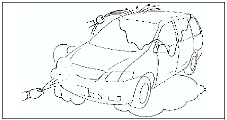
Vibration Method
1. If malfunction occurs or becomes worse while driving on a rough road or when engine is vibrating, perform the steps below.
Note
- There are several reasons vehicle or engine vibration could cause an electrical malfunction. Some of the things to check for are:
- Connectors not fully seated.
- Wire harnesses not having full play.
- Wires laying across brackets or moving parts.
- Wires routed too close to hot parts.
- An improperly routed, improperly clamped, or loose harness can cause wiring to become pinched between parts.
- The connector joints, points of vibration, and places where wire harnesses pass through the fire wall, body panels, etc. are the major areas to be checked.
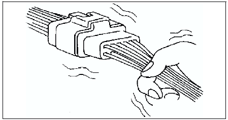
Inspection Method for Switch Connectors or Wires
1. Connect WDS or equivalent to DLC-2.
2. Turn ignition key to ON position (Engine OFF).
Note
- If engine starts and runs, perform the following steps at idle.
3. Access PIDs for the switch you are inspecting.
4. Turn switch on manually.
5. Shake each connector or wire harness a bit vertically and horizontally while monitoring the PID.
- If PID value is unstable, check for poor connection.
Inspection Method for Sensor Connectors or Wires
1. Connect WDS or equivalent to DLC-2.
2. Turn ignition switch to ON position (Engine OFF).
Note
- If engine starts and runs, perform the following steps at idle.
3. Access PIDs for the switch you are inspecting.
4. Shake each connector or wire harness a bit vertically and horizontally while monitoring the PID.
- If PID value is unstable, check for poor connection.
Inspection Method for Sensors
1. Connect WDS or equivalent to DLC-2.
2. Turn ignition switch to ON position (Engine OFF).
Note
- If engine starts and runs, perform the following steps at idle.
3. Access PIDs for the switch you are inspecting.
4. Vibrate the sensor slightly with your finger.
- If PID value is unstable or malfunction occurs, check for poor connection and/or poorly mounted sensor.
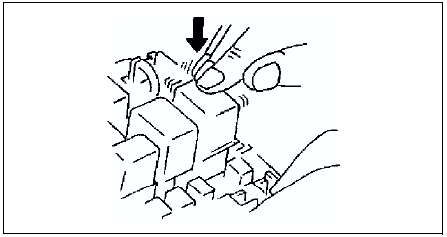
Inspection Method for Actuators or Relays
1. Connect WDS or equivalent to DLC-2.
2. Turn ignition switch to ON position (Engine OFF).
Note
- If engine starts and runs, perform the following steps at idle.
3. Prepare the Output State Control for actuators or relays that you are inspecting.
4. Vibrate the actuator or relay with your finger for 3 seconds
are Output State Control is activated.
- If variable click sound is heard, check for poor connection and/or poorly mounted actuator or relay.
Note
- Vibrating relays too strongly may result in open relays.
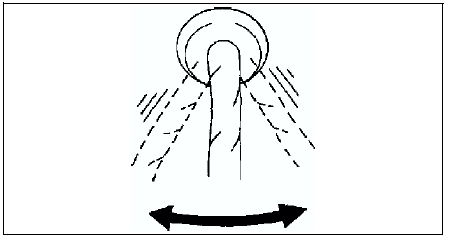
Water Sprinkling Method
Caution
- Indirectly change the temperature and humidity by spraying water onto the front of the radiator.
- If a vehicle is subject to water leakage, the leakage may damage the control module. When testing a vehicle with a water leakage problem, special caution must be used.
If malfunction occurs only during high humidity or rainy/snowy weather, perform the following steps.
1. Connect WDS or equivalent to DLC-2 if you are inspecting sensors or switches.
2. Turn ignition switch to ON position (Engine OFF).
Note
- If engine starts and runs, perform the following steps at idle.
3. Access PIDs for sensor or switch if you are inspecting sensors or switches.
4. If you are inspecting the switch, turn it on manually.
5. Spray water onto the vehicle or run it through a car wash.
- If PID value is unstable or malfunction occurs, repair or replace part as necessary.
 No.28 spark plug condition
Diagnostic procedure
...
 Engine control system operation inspection
Main Relay Operation Inspection
Verify that the main relay clicks when the ignition switch is turned to ON
position and off.
If there is no operation sound, inspect the following.
- Main ...
Other materials:
Mazda 6 Service Manual: Traction Control System (TCS)
The Traction Control System (TCS) enhances traction and safety by controlling
engine torque and braking. When the TCS detects driving wheel slippage, it lowers
engine torque and operates the brakes to prevent loss of traction.
This means that on a slick surface, the engine adjusts automatically ...
Mazda 6 Service Manual: Making a Call
Phonebook Usage
Telephone calls can be made by saying the contact name in the downloaded phonebook
or the name of a person whose phone number has been registered in the Bluetooth®
Hands-Free. Refer to Import contact (Download Phonebook).
1. Press the talk button.
2. Wait for the beep sound.
...