Mazda 6 Service Manual: Engine control system operation inspection
Main Relay Operation Inspection
Verify that the main relay clicks when the ignition switch is turned to ON position and off.
- If there is no operation sound, inspect the following.
- Main relay (See RELAY INSPECTION.)
- Harness and connector between ignition switch and main relay terminal A.
- Harness and connector between PCM terminal 2X and main relay terminal E.
Intake Manifold Vacuum Inspection
1. Verify air intake hoses are installed properly.
2. Start the engine and run it at idle.
3. Disconnect the vacuum hose between the intake manifold and purge solenoid valve from the intake manifold side.
4. Connect a vacuum gauge to the intake manifold and measure the intake manifold vacuum.
- If not as specified, inspect the following.
Specification
More than 60 kPa {450 mmHg, 18 inHg}
Note
- Air suction can be located by engine speed change when lubricant is sprayed on the area where suction is occurring.
- Air suction at throttle body, intake manifold and PCV valve installation points
- Accelerator cable free play
- Fuel injector insulator
- Engine compression (See COMPRESSION INSPECTION.)
Idle Air Control System Inspection
Engine coolant temperature compensation inspection
1. Connect WDS or equivalent to the DLC-2.
2. Select the following PIDs.
- ECT
- IAT
- RPM
3. Verify that the engine is in cold condition, then start the engine.
4. Verify that the engine speed decreases as the engine warms up.
- If the engine speed does not decrease or decreases slowly, inspect the following.
- ECT sensor and related harness (See ENGINE COOLANT TEMPERATURE (ECT) SENSOR INSPECTION.)
- IAC valve and related harness (See IDLE AIR CONTROL (IAC) VALVE INSPECTION.)
Load compensation inspection
1. Start the engine and run is at idle.
2. Connect WDS or equivalent to the DLC-2.
3. Verify that P0506, P0507 or P0511 not displayed.
- If P0506, P0507 or P0511 shown, carry out DTC inspection. (See DTC TABLE.)
4. Change the duty value of the IAC valve to 100%
using the IAC PID.
5. Verify that the idle speed increases.
- If the idle speed does not change, inspect the following.
- IAC valve air passage
- Open or short circuit between IAC valve connector terminals and PCM connector terminals 4G and 4J
6. Select the following PIDs.
- ACSW
- IAC
- PSP
- RPM
Note
- Excludes temporary idle speed drop just after the loads are turned on.
7. Verify that the engine speed is within the specification under each load condition.
- If not as specified specific load condition, inspect the following.
- A/C switch and related harness (See CLIMATE CONTROL UNIT INSPECTION.)
- Fan switch and related harness (See CLIMATE CONTROL UNIT INSPECTION.)
- PSP switch and related harness (See POWER STEERING PRESSURE (PSP) SWITCH INSPECTION.)
Engine speed
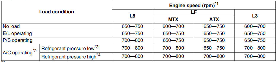
*1 :Neutral or P position
*2 :A/C switch and fan switch are on.
*3 :Refrigerant pressure switch (middle pressure) is off.
*4 :Refrigerant pressure switch (middle pressure) is on.
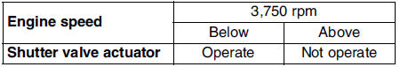
VIS Operation Inspection
1. Start the engine.
2. Inspect the rod operation under the following condition.
Rod operation
- If the rod operation is not as specified, inspect as follows.
(1) Stop the engine.
(2) Connect WDS or equivalent to the DLC-2.
(3)Verify that DTC P0661 or P0662 is not displayed.
- If DTC P0661 or P0662 is shown, carry out DTC inspection. (See DTC TABLE.)
(4) Turn ignition switch to ON.
(5) Turn the VIS control solenoid valve from on to off using the IVC PID and verify that operation sound of the solenoid valve is heard.
- If the operation sound is heard, inspect the following.
- Vacuum hose and vacuum chamber for looseness or damage
- Shutter valve actuator (See VARIABLE INTAKE-AIR SYSTEM (VIS) SHUTTER VALVE ACTUATOR INSPECTION (L3).)
- Shutter valve stuck open or close
- If the operation sound is not heard, inspect the following.
- VIS control solenoid valve (See VARIABLE INTAKE-AIR SYSTEM (VIS) CONTROL SOLENOID VALVE INSPECTION (L3).)
Variable Tumble Control System (VTCS) Operation Inspection
1. Connect the WDS or equivalent to the DLC-2.
2. Access ECT PID.
3. Verify that ECT PID is between 63°C {145°F} and 67°C {152°F}.
4. Start the engine.
5. Inspect rod operation under the following condition.
Rod operation
- If the rod operation is not specified, inspect as follows.
(1) Verify that DTC No. P2009 or P2010 is not displayed.
- If DTC No. P2009 or P2010 are shown, carry out DTC inspection. (See DTC TABLE.)
(2) Turn ignition switch to ON.
(3) Turn the VTCS solenoid valve from on to off using the IMRC PID and verify that operation sound of the solenoid valve is heard.
- If the operation sound is heard, inspect the following.
- Vacuum hose and vacuum chamber for looseness or damage
- Shutter valve actuator (See VARIABLE TUMBLE CONTROL SYSTEM (VTCS) SHUTTER VALVE ACTUATOR INSPECTION.)
- Shutter valve stuck open or close
- If the operation sound is not heard, inspect the following.
- VIS control solenoid valve (See VARIABLE TUMBLE CONTROL SOLENOID VALVE INSPECTION.)
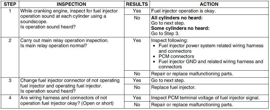
Fuel Injector Operation Inspection
Fuel Cut Control System Inspection
1. Warm up engine and let it idle.
2. Turn off the electrical loads and A/C switch.
3. Connect WDS or equivalent to the DLC-2.
4. Select RPM and FUELPW1 PIDs.
5. Monitor both PIDs while performing the following steps.
(1) Depress the accelerator pedal and increase the engine speed to 4,000 rpm.
(2) Release the accelerator pedal (brake pedal is not depressed) and verify that the fuel injector duration time is 0 msec
., and 2-5 msec.
when the engine speed drops below 1,200 rpm.
- If not as specified, inspect the following.
- ECT sensor and related harness (See ENGINE COOLANT TEMPERATURE (ECT) SENSOR INSPECTION.)
- Neutral/clutch switch and related harness (MTX) (See CLUTCH SWITCH INSPECTION.)
- TR switch and related harness (ATX) (See TRANSAXLE RANGE (TR) SWITCH INSPECTION.)
Fuel Pump Operation Inspection
1. Connect WDS or equivalent to the DLC-2.
2. Remove the fuel-filler cap.
3. Turn the ignition switch to ON position.
4. Turn the fuel pump relay from off to on using the FP PID and inspect if the operation sound is heard.
- If no operation sounds is heard, proceed to next step.
5. Measure the voltage at harness side fuel pump connector terminal B.
Specification
B+ (Ignition switch is on)
- If the voltage is as specified, inspect the following.
- Fuel pump continuity
- Fuel pump GND
- Wiring harness between fuel pump relay and PCM terminal 4P (without immobilizer system), 4Q (with immobilizer system)
- If not as specified, inspect the following.
- Fuel pump relay (See RELAY INSPECTION.)
- Wiring harness and connector (Main relay-fuel pump relay-fuel pump)
Fuel Pump Control System Inspection
1. Connect WDS or equivalent to the DLC-2.
2. Turn the ignition switch to ON position.
3. Select FP PID.
4. Turn the fuel pump relay from off to on and inspect if the operation sound of the fuel pump relay is heard.
- If no operation sound is heard, inspect the fuel pump relay.
- If the fuel pump relay is normal, inspect the following.
- Wiring harnesses and connectors (Main relay-fuel pump relay-PCM)
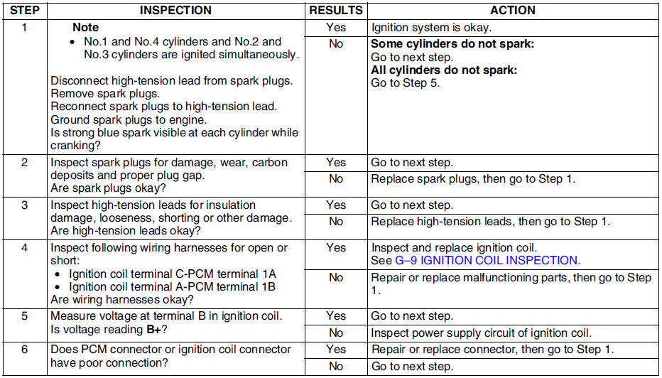
Spark Test
1. Remove the fuel pump relay.
2. Verify that each high-tension lead and connector is connected properly.
3. Inspect the ignition system in the following procedure.
Warning
- High voltage in the ignition system can cause strong electrical shock which can result in serious injury. Avoid direct contact to the vehicle body during the following spark test.
EGR Control System Inspection
1. Verify that EGR valve operation (initial operation) sound is heard when the ignition switch is turned to ON position.
- If the operation sound is not heard, connect WDS or equivalent to the DLC-2 and verify that the DTC P0403 is shown. Carry out DTC inspection. (See DTC TABLE.)
2. Start the engine and run it at idle.
3. Increase the step value of EGR valve from 0 to 40 using SEGRP PID.
4. Operate the EGR valve and inspect if the engine speed becomes unstable or the engine stalls.
- If the engine speed will not change, proceed to following.
(1) Stop the engine.
(2) Remove the EGR valve.
(3) Connect the EGR valve connector.
(4) Turn the ignition switch to ON.
(5) Increase the step value of EGR valve from 0 to 40 using SEGRP PID.
(6) Inspect the EGR operation.
- If the EGR valve is operated, clean the EGR valve and reinspect from Step 2.
- If the EGR valve will not operate, replace the EGR valve and reinspect from Step 2.
5. Warm up the engine to normal operating temperature.
6. Select the following PIDs.
- ECT
- RPM
- SEGRP
- TP
- VSS
7. Let the vehicle idle and verify that the SEGRP value is 0.
8. Put the vehicle in drive.
9. Depress the accelerator pedal and verify that the SEGRP value is increased.
- If the SEGRP value will not increase, inspect the VSS, TP and ECT PIDs. (See PCM INSPECTION.)
10. Stop the vehicle and verify that the SEGRP value is returned 0.
Purge Control System Inspection
1. Start the engine.
2. Disconnect the vacuum hose between the purge solenoid valve and the charcoal canister.
3. Put a finger to the purge solenoid valve and verify that there is no vacuum applied when the engine is cold.
- If there is a vacuum, inspect the following.
- Wiring harness and connectors (Purge solenoid valve-PCM terminal 4U)
- Purge solenoid valve
4. Warm up the engine to the normal operating temperature.
5. Stop the engine.
6. Connect WDS or equivalent to the DLC-2 and verify that the DTC P0443 is shown. Carry out DTC inspection. (See DTC TABLE.)
7. Turn the ignition switch to ON position.
8. Select ECT PID.
9. Verify that the engine coolant temperature is above 60°C {140°F}.
- If WDS or equivalent indicates below 60°C {140°F}
, carry out the ECT sensor inspection.
10. Select EVAPCP PID.
11. Increase the duty value of the purge solenoid valve to 50%
and inspect if the operation sound of the valve is heard.
- If the operation sound is heard, inspect for the loose or damaged vacuum hose. (Intake manifold-purge solenoid valve-charcoal canister)
- If the operation sound is not heard, carry out the purge solenoid valve inspection.
A/C Cut-off Control System Inspection
1. Start the engine.
2. Turn the A/C switch and fan switch on.
3. Verify that the A/C compressor magnetic clutch actuates.
- If it does not actuate, go to symptom troubleshooting No.23 A/C does not work sufficiently.
4. Fully open the throttle valve and verify that the A/C compressor magnetic clutch does not actuate for 2-5 seconds.
- If it actuates, inspect as follows.
(1) Connect WDS or equivalent to the DLC-2.
(2) Turn the A/C switch off.
(3) Turn the ignition switch to ON position.
(4) Select ACCS PID.
(5) Turn the A/C relay from off to on and inspect if the operation sound of the relay is heard.
- If the operation sound is heard, inspect TP PID.
- If the operation sound is not heard, inspect following.
- A/C relay
- Open or short to GND circuit in wiring harness and connectors (Ignition switch-A/C relay-PCM terminal 4O)
- A/C related parts
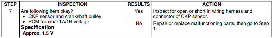
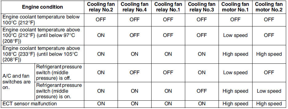
Cooling Fan Control System Inspection
L8, LF (General area) engine model
Cooling fan system operation
Cooling fan relay No.1
1. Connect WDS or equivalent to DLC-2.
2. Verify that ECT PID is below cooling fan operating temperature.
3. Verify that A/C switch and fan switch are off.
4. Turn the ignition switch to ON position.
5. Verify that the cooling fan is not operating.
- If the cooling fan No.1 is operating:
(1) Select FAN3 PID.
(2) Send OFF and verify the cooling fan is off.
- If the cooling fan is on, inspect the following.
- Cooling fan relay stuck in closed position
- Short to GND circuit between cooling fan relay and PCM terminal 4L
- Short to power in circuit at cooling fan relay
- DTC for ECT sensor (P0117, P0118)
- If the cooling fan is off, inspect the following.
- Short to GND circuit between refrigerant pressure switch and PCM terminal 1AC
- DTC for ECT sensor (P0117, P0118)
6. Start the engine.
7. Verify that the cooling fan is operating when engine is hot.
- If the cooling fan does not operate, perform the following.
1. Connect WDS or equivalent to the DLC-2.
2. Select FAN3 PID.
3. Operate cooling fan by sending ON command.
4. Inspect if the operation sound is heard from the cooling fan relay.
- If the operation sound is heard, inspect the wiring harness, connectors and cooling fan motor.
- If the operation sound is not heard, inspect cooling fan relay and open circuit wiring harness and connectors.
8. Turn the A/C switch and fan switch on.
9. Verify that cooling fan is operating.
- If fan does not operate, inspect A/C system.
Cooling fan relay No.2
1. Verify that A/C switch and fan switch are off.
2. Start the engine and let it idle.
3. Verify that the cooling fan No.2 is not operating.
- If condenser fan is operating, inspect for the following.
- Cooling fan relay No.2 is stuck in closed position.
- Short to power in circuit between condenser fan relay and condenser fan
- Short to GND in circuit between refrigerant pressure switch and PCM terminal 1AC
- Short to GND circuit between condenser fan relay and PCM terminal 4B
4. Turn the A/C switch and fan switch on.
5. Verify that the cooling fan No.2 is operating and operation sound of A/C compressor magnetic clutch is heard.
6. Turn the A/C switch and fan switch off.
- If the cooling fan No.2 does not operate but operation sound of A/C compressor magnetic clutch is heard, inspect for the following.
- Open circuit between ignition switch and cooling fan relay No.2
- Open circuit between battery and cooling fan relay No.2
- Open circuit between cooling fan relay No.2 and PCM terminal 4B
- Open circuit between cooling fan relay No.2 and cooling fan motor No.2 or fan motor GND
- Cooling fan relay No.2 is stuck open.
- Cooling fan motor No.2
- If both cooling fan No.2 and A/C compressor do not operate, inspect the following.
- TP PID
- A/C system
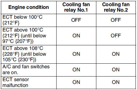
L3 engine models
Cooling fan system operation (at idle)
1. Connect WDS or equivalent to DLC-2.
2. Verify that ECT PID is below cooling fan operating temperature.
3. Verify that the A/C switch and fan switch are off.
4. Start the engine and let it at idle.
5. Verify that the cooling fan and condenser fan are not operating.
- If the cooling fan and condenser fan are operating low speed, inspect for following:
- Short to GND circuit between PCM terminal 4L and cooling fan relay No.2
- Cooling fan relay No.2 stuck in closed position
- If the cooling fan and condenser fan are operating high speed, inspect for following:
- DTC for ECT sensor (P0117, P0118)
- If the cooling fan is not operating and condenser fan is operating, inspect for following:
- Short to GND circuit between PCM terminal 4F and transfer relay
- Transfer relay stuck ON position
- Short to GND circuit between PCM terminal 4B and cooling fan relay No.3
- Condenser fan relay stuck ON
6. Start the engine.
7. Verify that the cooling fan and condenser fan are operating low speed when ECT PID is above 100°C {212°F}.
- If the cooling fans does not operate, perform the following:
1. Select FAN3 PID.
2. Operate cooling fan relay No.2 by sending ON command.
3. Inspect the operation sound is heard from cooling fan relay No.2.
- If the operation sound is heard, inspect wiring harnesses, connectors, transfer relay and cooling and condenser fan motor.
- If the operation sound is not heard, inspect cooling fan relay No.2 and open circuit between PCM terminal 4L and cooling fan relay No.2 wiring harness and connectors.
- Inspect the cooling fan is operating high speed, inspect the following:
- Short to GND circuit between PCM terminal 4F and cooling fan relay No.4/cooling fan relay No.1.
- Cooling fan relay stuck closed position
- If the condenser fan is operating high speed, inspect the following:
- Short to GND circuit between PCM terminal 4F and cooling fan relay No.4/cooling fan relay No.1
- cooling fan relay No.1 stuck ON position
8. Turn A/C switch and fan switch are on.
9. Verify that the ACCS PID is ON.
- If the ACCS PID is not ON, inspect for following:
- A/C switch
- Fan switch
- Refrigerant pressure switch
- Open circuit PCM 1AC related harnesses and connectors
10.Access the COLP PID.
11. Verify that the cooling fan is operating high speed an condenser fan is operating low speed, while the COLP PID is ON.
- If the cooling fan and condenser fan are operating low speed, perform the following:
1. Select FAN1 PID.
2. Operate cooling fan relay No.4 and transfer relay by sending ON command.
3. Inspect the operation sound is heard from cooling fan relay No.4 and cooling fan relay No.1.
- If the operation sound is not heard from cooling fan relay No.4, inspect cooling fan relay No.4 and open circuit between PCM 4F and cooling fan relay No.4 wiring harnesses and connectors.
- If the operation sound is not heard from cooling fan relay No.1, inspect cooling fan relay No.1 and between PCM terminal 4F and cooling fan relay No.1 wiring harnesses and connector.
- If the operation sound is heard from cooling fan relay No.4 and cooling fan relay No.1, inspect wiring harnesses and connectors.
- If the cooling fan motor No.2 does not operate, perform the following:
- Cooling fan motor No.2 and related wiring harnesses and connectors
12. Verify that the cooling fan motor No.1 is operating low speed and the cooling fan motor No.1 is operating high speed, while the COLP PID is OFF.
- If the cooling fan motor No.1 and cooling fan motor No.2 are operating low seed, perform the following:
1. Select FAN1 PID.
2. Operate cooling fan relay 3 by sending ON command.
3. Inspect the operation sound is heard from cooling fan relay No.3.
- If the operation sound is heard, inspect wiring harnesses and connectors.
- If the operation sound is not heard, inspect coooling fan relay No.3 and open circuit wiring arnesses and connectors between PCM terminal 4B and coooling fan relay No.3.
L8, LF (Intensely hot area) engine models
Cooling fan system operation (at idle)
1. Connect WDS or equivalent to DLC-2.
2. Verify that ECT PID is below cooling fan operating temperature.
3. Verify that the A/C switch and fan switch are off.
4. Start the engine and let it at idle.
5. Verify that the cooling fans fan are not operating.
- If the cooling fan is operating low speed, inspect for following:
- Short to GND circuit between PCM terminal 4L and cooling fan relay No.2
- Cooling fan relay No.2 stuck in closed position
- If the cooling fans are operating high speed, inspect for following:
- DTC for ECT sensor (P0117, P0118)
- If the cooling fan motor No.1 is not operating and cooling fan motor No.2 is operating, inspect for following:
- Short to GND circuit between PCM terminal 4F and cooling fan relay No.1
- Cooling fan relay No.1 stuck ON
- Short to GND circuit between PCM terminal 4B and cooling fan relay No.3
- Cooling fan relay No.3 stuck ON
6. Start the engine.
7. Verify that the cooling fans are operating low speed when ECT PID is above 100°C {212°F}.
- If the cooling fan motor No.1 does not operate, perform the following:
1. Select FAN3 PID.
2. Operate cooling fan relay No.2 by sending ON command.
3. Inspect the operation sound is heard from cooling fan relay No.2.
- If the operation sound is heard, inspect wiring harnesses, connectors and cooling fan motor No.1.
- If the operation sound is not heard, inspect cooling fan relay No.2 and open circuit between PCM terminal 4L and cooling fan relay No.2 wiring harness and connectors.
- Inspect the cooling fan is operating high speed, inspect the following:
- Short to GND circuit between PCM terminal 4F and cooling fan relay No.1/cooling fan relay No.4.
8. Turn A/C switch and fan switch are on.
9. Verify that the ACCS PID is ON.
- If the ACCS PID is not ON, inspect for following:
- A/C switch
- Fan switch
- Refrigerant pressure switch
- Open circuit PCM 1AC related harnesses and connectors
10. Access the COLP PID.
11. Verify that the cooling fan motor No.1 is operating high speed and cooling fan motor No.2 is operating low speed, while the COLP PID is ON.
- If the cooling fan motor No.1 does not operate high speed, perform the following:
1. Select FAN1 PID.
2. Operate cooling fan relay No.1 and cooling fan relay No.4 by sending ON command.
3. Inspect the operation sound is heard from cooling fan relay No.1 and cooling fan relay No.4.
- If the operation sound is not heard from cooling fan relay No.4, inspect cooling fan relay No.4 and open circuit between PCM 4F and cooling fan relay No.4 wiring harnesses and connectors.
- If the operation sound is not heard from cooling fan relay No.1, inspect cooling fan relay No.1 and between PCM terminal 4F and cooling fan relay No.1 wiring harnesses and connector.
- If the operation sound is heard from cooling fan relay No.1 and cooling fan relay No.4, inspect wiring harnesses and connectors.
- If the cooling fan motor No.2 does not operate, perform the following:
- Inspect cooling fan motor No.2 and related wiring harnesses and connectors
- If the cooling fan motor No.2 does not operate, perform the following:
1. Select FAN2 PID.
2. Operate cooling fan relay No.3 by sending ON command.
3. Inspect the operation sound is heard from cooling fan relay No.3.
- If the operation sound is heard, inspect wiring harnesses and connectors.
- If the operation sound is not heard, inspect cooling fan relay No.3 and open circuit wiring harnesses and connectors between PCM terminal 4B and cooling fan relay No.3.
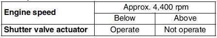
Variable Air Duct (VAD) Control System Operation Inspection (L3 Engine Models)
1. Connect WDS or equivalent to DLC-2.
2. Access ECT, TP and RPM PIDs.
3. Start the engine.
4. Verify ECT PID is 70°C {158°F} or over.
5. Inspect shutter valve operation following condition.
VAD shutter valve operation
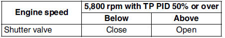
- If the shutter valve operation is not specified, inspect as follows.
(1) Verify that DTC P1410 is not displayed.
- If DTC P1410 is shown, carry out DTC inspection. (See DTC TABLE.)
(2) Turn ignition switch to ON.
(3) Turn the VAD control solenoid valve from on to off using the VAD PID and verify that operation sound of the solenoid valve is heard.
- If the operation sound is heard, inspect the following.
- Vacuum hose looseness or damage
- Vacuum chamber crack or damage
- Shutter valve actuator. (See VARIABLE AIR DUCT (VAD) SHUTTER VALVE INSPECTION (L3).)
- Shutter valve stuck open or close
- If the operation sound is not heard, inspect following.
- VAD control solenoid valve. (See VARIABLE AIR DUCT (VAD) CONTROL SOLENOID VALVE INSPECTION (L3).)
Variable Valve Timing Control System Operation Inspection
When idling cannot be continued
1. Remove the oil control valve (OCV) and verify that the spool valve is at maximum retard position.
2. If the spool valve is stuck in advance direction, replace the oil control valve (OCV).
3. Connect the oil control valve (OCV).
4. Turn the ignition switch on.
5. Verify that the spool valve is at maximum retard position.
6. If the spool valve is stuck in advance direction, inspect for the following.
- Short circuit in harnesses or connectors between the oil control valve (OCV) and the PCM.
7. Inspect the variable valve timing actuator.
When idling can be continued
1. Warn up the engine.
2. Connect WDS or equivalent to DLC-2.
3. Idle the engine.
4. Select VT DUTY1 PID.
5. Set the oil control valve (OCV) duty valve to 100% and verify that the engine idles roughly or stalls.
- If as specified, inspect the timing belt component (valve timing deviation).
- If not as specified, go to next step.
6. Remove the oil control valve (OCV) and connect the oil control valve (OCV) connector to the oil control valve (OCV).
7. Turn ignition switch to ON.
8. Select VT DUTY1 PID.
9. Set the oil control valve (OCV) duty value to 100% and verify that the spool valve operates in the advance direction.
10. If not as specified, inspect the following.
- Oil control valve (OCV) operation.
- Harnesses and connectors between the oil control valve (OCV) and the PCM for open or short.
11. Inspect the following hydraulic passages for clogging and/or leakage.
- Oil pressure switchoil control valve (OCV)
- Oil control valve (OCV)camshaft
- Camshaft internal passage
12. If they are okay, replace the intake camshaft pulley (with a built-in variable valve timing actuator).
 Intermittent concern troubleshooting
Vibration Method
1. If malfunction occurs or becomes worse while driving on a rough road or
when engine is vibrating, perform the steps below.
Note
There are several reasons vehicle or ...

Other materials:
Mazda 6 Service Manual: Rear door trim removal/installation
1. Disconnect the negative battery cable if equipped with power window
system.
2. Remove the regulator handle if equipped.
3. Open the cap using a small screwdriver, then remove the screw.
4. Remove the inner handle cover.
5. Remove the cover, then remove screw.
6. Disengage clips A from th ...
Mazda 6 Service Manual: Fuel Economy Monitor
The Control Status and Fuel Consumption are switched and displayed by operating
each icon in the display.
In addition, after completing a trip, the total energy efficiency to date is
displayed in the ending display when the ending display is turned on.
1. Select the icon on the home
screen ...